
Page 268 - Electromechanical Devices and Components Illustrated Sourcebook
P. 268
230 Electromechanical Devices & Components Illustrated Sourcebook
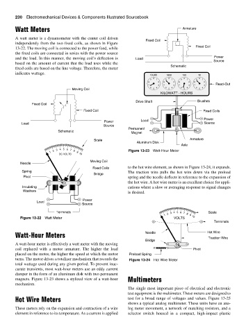
Watt Meters Armature
A watt meter is a dynamometer with the center coil driven
Fixed Coil
independently from the two fixed coils, as shown in Figure
13-22. The moving coil is connected to the power feed, while Fixed Coil
the fixed coils are connected in series with the power source
Power
and the load. In this manner, the moving coil’s deflection is Load Source
based on the amount of current that the load uses while the
Schematic
fixed coils are based on the line voltage. Therefore, the meter
indicates wattage.
10,000 1000 100 10
0 0 0 0
9 1 9 1 9 1 9 1
8 2 8 2 8 2 8 2
7 3 7 3 7 3 7 3 Read-Out
6 4 6 4 6 4 6 4
Moving Coil 5 5 5 5
KILOWATT - HOURS
Drive Shaft Brushes
Fixed Coil
Fixed Coil Fixed Coils
Power Load Power
Load Source
Source
Permanent
Schematic
Magnet
Scale Armature
Aluminum Disk
Axle
1 2 3 4 5 6 7 8 9 Figure 13-23 Watt-Hour Meter
DC VOLTS 10
Moving Coil
Needle
Fixed Coils to the hot wire element, as shown in Figure 13-24, it expands.
Spring The traction wire pulls the hot wire down via the preload
Bridge
Pivot spring and the needle deflects in reference to the expansion of
the hot wire. A hot wire meter is an excellent choice for appli-
Insulating cations where a slow or averaging response to signal changes
Washers
is desired.
Power
Load
Source
Terminals 4 Scale
1 2 3 5 6 7 8 9
Figure 13-22 Watt Meter VOLTS 10
Terminals
Watt-Hour Meters Needle Hot Wire
Bridge Traction Wire
A watt-hour meter is effectively a watt meter with the moving
coil replaced with a motor armature. The higher the load Pivot
placed on the motor, the higher the speed at which the motor Preload Spring
turns. The motor drives a totalizer mechanism that records the Figure 13-24 Hot Wire Meter
total wattage used during any given period. To prevent inac-
curate transients, most watt-hour meters use an eddy current
damper in the form of an aluminum disk with two permanent
magnets. Figure 13-23 shows a stylized view of a watt-hour Multimeters
mechanism.
The single most important piece of electrical and electronic
test equipment is the multimeter. These meters are designed to
Hot Wire Meters test for a broad range of voltages and values. Figure 13-25
shows a typical analog multimeter. These units have an ana-
These meters rely on the expansion and contraction of a wire log meter movement, a network of matching resistors, and a
element in reference to its temperature. As a current is applied selector switch housed in a compact, high-impact plastic