
Page 273 - Electromechanical Devices and Components Illustrated Sourcebook
P. 273
Chapter 13 Meters 235
Moving Jaw Fixed Jaw Moving Jaw Fixed Jaw
20 50
10 100
Pivot Range Selector
500 AMPS MAX. Palm Grip Trigger 7 6 5 14 12 10 35 Multirange Scale
45
Trigger −10 9 8 20 18 16 50
40
30
25
Handle
15
10
2 4 3 8 6 4 20 Pointer
1 2 5
0 0 0
Bend Relief
Test Lead Wire Figure 13-40 Hand Held Inductive Current Meter
Output Terminals
(M) Banana Plugs
Figure 13-38 Inductive Pickup
Through Hole
Cable to be
Moving Core or Jaw Monitored Secondary Coil
Iron Core
Secondary
Base
Figure 13-41 Commercial Current Transformer
Volt Meter
Voltmeter
Pivot
Cable in which
Current is to be Measured
Figure 13-39 Inductive Pickup Schematic
Flow of Current
Shunt Resistor
Figure 13-42 Current Shunt Schematic
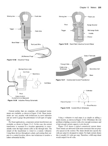
Current probes that are complete, self-contained instru-
ments are available, as shown in Figure 13-40. These instru-
ments are very popular with technicians in most industries
and are used to gauge the performance of all types of equip- Using a voltmeter to read amps is as simple as adding a
ment. shunt resistor, as shown in Figure 13-42. Oftentimes the real
For fixed applications, component current transformers are problem is finding a resistor with a low enough resistance and
available, as shown in Figure 13-41. In this case, the current a high enough current capacity to do the job.
transformer is mounted in a location appropriate to conve- Figure 13-43 shows a typical commercial current shunt.
niently route the high-current cable in the through hole. The These shunts are delivered with meter terminals that are prop-
output of the transformer is wired to a remote voltmeter. erly spaced on the resistor. The shunt should also specify the
Using these devices throughout a plant, and routing their out- volts per amp it is designed to output. For high current shunts
puts to a central location, allows one technician to monitor a this is usually 0.1 volts per amp. Therefore, a 600-amp shunt
rather substantial facility. would output 0 to 60 volts.