
Page 277 - Electromechanical Devices and Components Illustrated Sourcebook
P. 277
Chapter 13 Meters 239
Voltmeter Normally a decade resistance box, as discussed in Chapter 4,
is set up as one of the known resistors. In this manner, the
Battery
range of the bridge can easily be adjusted. The variable resis-
V
tor is generally a calibrated test unit. Using a digital multime-
ter and progressively selecting lower voltage ranges can make
an extremely accurate measurement.
Resistor to be
Measured
A
The SlideWire Bridge
Ampmeter
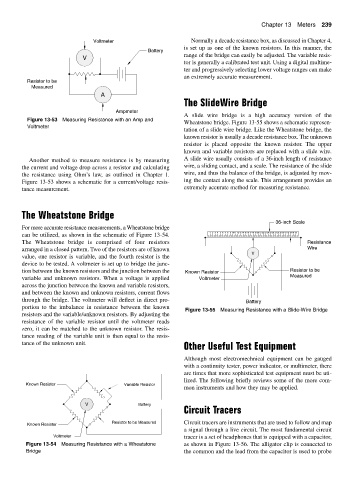
A slide wire bridge is a high accuracy version of the
Figure 13-53 Measuring Resistance with an Amp and
Wheatstone bridge. Figure 13-55 shows a schematic represen-
Voltmeter
tation of a slide wire bridge. Like the Wheatstone bridge, the
known resistor is usually a decade resistance box. The unknown
resistor is placed opposite the known resistor. The upper
known and variable resistors are replaced with a slide wire.
Another method to measure resistance is by measuring A slide wire usually consists of a 36-inch length of resistance
the current and voltage drop across a resistor and calculating wire, a sliding contact, and a scale. The resistance of the slide
the resistance using Ohm’s law, as outlined in Chapter 1. wire, and thus the balance of the bridge, is adjusted by mov-
Figure 13-53 shows a schematic for a current/voltage resis- ing the contact along the scale. This arrangement provides an
tance measurement. extremely accurate method for measuring resistance.
The Wheatstone Bridge
36-inch Scale
For more accurate resistance measurements, a Wheatstone bridge
can be utilized, as shown in the schematic of Figure 13-54. 123456789 10 11 12 13 14 15 16 17 18 19 20 21 22 23 24 25 26 27 28 29 30 31 32 33 34 35
The Wheatstone bridge is comprised of four resistors Resistance
arranged in a closed pattern. Two of the resistors are of known Wire
V
value, one resistor is variable, and the fourth resistor is the
device to be tested. A voltmeter is set up to bridge the junc-
tion between the known resistors and the junction between the Known Resistor Resistor to be
variable and unknown resistors. When a voltage is applied Voltmeter Measured
across the junction between the known and variable resistors,
and between the known and unknown resistors, current flows
through the bridge. The voltmeter will deflect in direct pro- Battery
portion to the imbalance in resistance between the known
Figure 13-55 Measuring Resistance with a Slide-Wire Bridge
resistors and the variable/unknown resistors. By adjusting the
resistance of the variable resistor until the voltmeter reads
zero, it can be matched to the unknown resistor. The resis-
tance reading of the variable unit is then equal to the resis-
tance of the unknown unit.
Other Useful Test Equipment
Although most electromechnical equipment can be gauged
with a continuity tester, power indicator, or multimeter, there
are times that more sophisticated test equipment must be uti-
lized. The following briefly reviews some of the more com-
Known Resistor Variable Resistor
mon instruments and how they may be applied.
V Battery
Circuit Tracers
Resistor to be Measured Circuit tracers are instruments that are used to follow and map
Known Resistor
a signal through a live circuit. The most fundamental circuit
Voltmeter tracer is a set of headphones that is equipped with a capacitor,
Figure 13-54 Measuring Resistance with a Wheatstone as shown in Figure 13-56. The alligator clip is connected to
Bridge the common and the lead from the capacitor is used to probe