
Page 282 - Electromechanical Devices and Components Illustrated Sourcebook
P. 282
244 Electromechanical Devices & Components Illustrated Sourcebook
Most people consider vacuum tubes to be electronic devices;
Vacuum Envelope
however, they are very much electromechanical devices. A
vacuum tube takes advantage of the fact that a glowing fila- −
ment, when properly biased, will emit electrons. Figure 14-1 Anode V Voltmeter
shows a demonstration of this phenomenon. The glowing fila- Cathode (Filament)
+
ment is a piece of coiled nichrome wire. When the switch is
closed, the filament starts to glow and a voltage can be observed
on the voltmeter. When the switch is opened, the filament
cools off and the voltage returns to zero. When the coil and
plate are in air, most of the electrons emitted will instanta-
neously reattach to the gases that make up the air. To eliminate Filament Meter
Supply Supply
reattachment and improve the flow of electrons, the inside of
a vacuum tube is evacuated of all gases. In the absence of any Figure 14-2 Vacuum Tube Diode Circuit
gases, the electrons are free to travel across the components of
the vacuum tube.
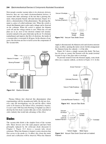
supply is disconnected, the filament cools and electron emission
stops, in effect, opening the meter circuit. In this arrangement
the filament forms the cathode (–) of the tube.
Voltmeter Figure 14-3 shows a simple vacuum tube diode. The base
has two pins to connect the filament with the anode terminal
Plate 1 2 3 4 5 located on top of the glass tube or envelope.
− − − DC VOLTS
− − − − To provide isolation from the filament supply, some diode
Electron Emission
tubes use a separate cathode, as shown in Figure 14-4. In this
Glowing Filament − +
Anode Terminal
− + − +
Anode
Switch
Cathode (Filament)
Batteries
Vacuum Tube Envelope
Figure 14-1 Electron Emission
Base
Thomas Edison first observed this phenomenon when Cathode/Filament Terminals
experimenting with his incandescent bulbs. He did not, how-
ever, carry the investigations very far and the effect, which Figure 14-3 Vacuum Tube Diode
came to be known as the Edison effect, remained a mystery.
It wasn’t until 1905 that John Fleming of England was able to
develop the first diode vacuum tube and, in turn, launched an
Vacuum
entire industry that would take advantage of the effect. Envelope
Coated
Anode Surface −
Cathode
Diodes Isolated Filament V Voltmeter
The vacuum tube diode is the simplest form of the vacuum +
tube. These devices serve the same purpose and have been
principally replaced by the solid-state diode discussed in
Chapter 4. Figure 14-2 shows a vacuum tube circuit
schematic. When the filament is heated, it emits electrons that Filament Supply Meter Supply
flow across to the anode (+). In effect, this closes the meter Figure 14-4 Vacuum Tube Diode Circuit with an Isolated
circuit and a deflection will be observed. When the filament Filament