
Page 285 - Electromechanical Devices and Components Illustrated Sourcebook
P. 285
Chapter 14 Vacuum Tubes 247
Anode Terminal
Ignitor Terminal
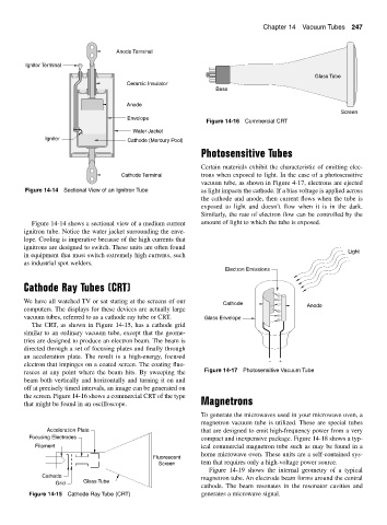
Glass Tube
Ceramic Insulator
Base
Anode
Screen
Envelope
Figure 14-16 Commercial CRT
Water Jacket
Ignitor Cathode (Mercury Pool)
Photosensitive Tubes
Certain materials exhibit the characteristic of emitting elec-
Cathode Terminal trons when exposed to light. In the case of a photosensitive
vacuum tube, as shown in Figure 4-17, electrons are ejected
Figure 14-14 Sectional View of an Ignitron Tube as light impacts the cathode. If a bias voltage is applied across
the cathode and anode, then current flows when the tube is
exposed to light and doesn’t flow when it is in the dark.
Similarly, the rate of electron flow can be controlled by the
Figure 14-14 shows a sectional view of a medium current amount of light to which the tube is exposed.
ignitron tube. Notice the water jacket surrounding the enve-
lope. Cooling is imperative because of the high currents that
ignitrons are designed to switch. These units are often found
Light
in equipment that must switch extremely high currents, such
as industrial spot welders.
Electron Emissions
Cathode Ray Tubes (CRT)
−
We have all watched TV or sat staring at the screens of our −
Cathode − Anode
computers. The displays for these devices are actually large −
vacuum tubes, referred to as a cathode ray tube or CRT. Glass Envelope − −
The CRT, as shown in Figure 14-15, has a cathode grid
similar to an ordinary vacuum tube, except that the geome-
tries are designed to produce an electron beam. The beam is
directed through a set of focusing plates and finally through
an acceleration plate. The result is a high-energy, focused − +
electron that impinges on a coated screen. The coating fluo-
resces at any point where the beam hits. By sweeping the Figure 14-17 Photosensitive Vacuum Tube
beam both vertically and horizontally and turning it on and
off at precisely timed intervals, an image can be generated on
the screen. Figure 14-16 shows a commercial CRT of the type
that might be found in an oscilloscope. Magnetrons
To generate the microwaves used in your microwave oven, a
magnetron vacuum tube is utilized. These are special tubes
Acceleration Plate that are designed to emit high-frequency power from a very
Focusing Electrodes compact and inexpensive package. Figure 14-18 shows a typ-
Filament ical commercial magnetron tube such as may be found in a
home microwave oven. These units are a self-contained sys-
Fluorescent
Screen tem that requires only a high-voltage power source.
Figure 14-19 shows the internal geometry of a typical
Cathode magnetron tube. An electrode beam forms around the central
Glass Tube
Grid
cathode. The beam resonates in the resonator cavities and
Figure 14-15 Cathode Ray Tube (CRT) generates a microwave signal.