
Page 288 - Electromechanical Devices and Components Illustrated Sourcebook
P. 288
250 Electromechanical Devices & Components Illustrated Sourcebook
The electromechanical marriage plays an important role in Trigger Circuit
detecting the real world. Most electrical sensors are employed
to detect or monitor a physical attribute and, therefore, must Output
be electromechanical in nature. The simplest form of these
sensors is the limit switch, such as the button that detects
Inductive
when the refrigerator’s door is open. Your automobile has a Pickup
wide variety of sophisticated transducers that monitor all
aspects of engine operation. Home heating and air-conditioning
systems rely on various sensors to keep them operating at
Battery
peak efficiency. Sensors provide a necessary interface between
the mechanical and electrical worlds.
Ferrous Component
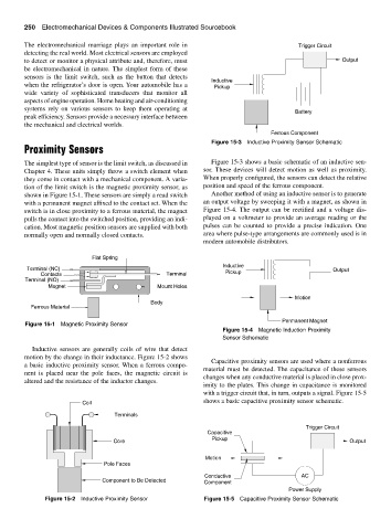
Figure 15-3 Inductive Proximity Sensor Schematic
Proximity Sensors
The simplest type of sensor is the limit switch, as discussed in Figure 15-3 shows a basic schematic of an inductive sen-
Chapter 4. These units simply throw a switch element when sor. These devices will detect motion as well as proximity.
they come in contact with a mechanical component. A varia- When properly configured, the sensors can detect the relative
tion of the limit switch is the magnetic proximity sensor, as position and speed of the ferrous component.
shown in Figure 15-1. These sensors are simply a read switch Another method of using an inductive sensor is to generate
with a permanent magnet affixed to the contact set. When the an output voltage by sweeping it with a magnet, as shown in
switch is in close proximity to a ferrous material, the magnet Figure 15-4. The output can be rectified and a voltage dis-
pulls the contact into the switched position, providing an indi- played on a voltmeter to provide an average reading or the
cation. Most magnetic position sensors are supplied with both pulses can be counted to provide a precise indication. One
normally open and normally closed contacts. area where pulse-type arrangements are commonly used is in
modern automobile distributors.
Flat Spring
Inductive
Terminal (NC) Output
Contacts Terminal Pickup
Terminal (NO)
Magnet Mount Holes
Motion
Body
Ferrous Material
Permanent Magnet
Figure 15-1 Magnetic Proximity Sensor
Figure 15-4 Magnetic Induction Proximity
Sensor Schematic
Inductive sensors are generally coils of wire that detect
motion by the change in their inductance. Figure 15-2 shows
Capacitive proximity sensors are used where a nonferrous
a basic inductive proximity sensor. When a ferrous compo-
material must be detected. The capacitance of these sensors
nent is placed near the pole faces, the magnetic circuit is
changes when any conductive material is placed in close prox-
altered and the resistance of the inductor changes.
imity to the plates. This change in capacitance is monitored
with a trigger circuit that, in turn, outputs a signal. Figure 15-5
shows a basic capacitive proximity sensor schematic.
Coil
Terminals
Trigger Circuit
Capacitive
Pickup
Core Output
Motion
Pole Faces
Conductive AC
Component to Be Detected Component
Power Supply
Figure 15-2 Inductive Proximity Sensor Figure 15-5 Capacitive Proximity Sensor Schematic