
Page 291 - Electromechanical Devices and Components Illustrated Sourcebook
P. 291
Chapter 15 Sensors 253
Mounting Holes
Wind Vane
Rotating Brush
Copper Pad
Copper Slip Ring
Fixed Brush
Connector
Hub
PC Board
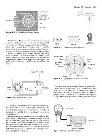
Figure 15-15 PC Board Rotary Position Indicator
NE
Printed Circuit (PC) board rotary position indicators provide
Digital
a simple method to construct low-cost resolvers. Figure 15-15 Panel Potentiometer
shows a typical PC board rotary position indicator. This par- Indicator Controller
ticular unit is a single-pole, 15-position unit. It should be Figure 15-17 Digital Wind Direction Indicator
noted that these types of positioners can be configured to have
several tracts, with specific positions and/or base two outputs.
Figure 15-16 shows a typical application for a PC board
position indicator. The hub of the sensor is mounted to the
Mounting Holes
shaft of a wind vane. The outputs are wired to a circular array
of panel lights, which indicate the points of the compass. The Z Ring X Ring
panel lights continuously indicate the position of the wind Rotor
Adjustable
vane. Pivots Z Resolver
X Resolver
Y Ring
Wind Vane
Frame Y Resolver
Figure 15-18 Digital Gyroscope Position Indication
nnw N nne
NW NE
nww nee One of the most common rotational parameters to monitor
Panel W E Position
sww see is revolutions per minute (RPM). This can easily be accom-
Indicator SW SE On/Off Indicator
ssw S sse
Battery plished by using a generator and voltmeter, as shown in
Figure 15-19. The faster the generator is turned, the higher the
voltage reading. The displayed volts correspond directly with
the input RPM of the generator. Standard generators rarely
Figure 15-16 Wind Direction Indicator
A wind position indicator can be configured using a digi-
500 1000 1500
tal potentiometer, as shown in Figure 15-17. In this case the 2000
RPM Voltmeter
output of the potentiometer is connected to a controller or
computer. The controller drives a panel display that indicates
wind direction. − +
Detecting motion in three dimensions is generally the duty
of a gyroscope. These detectors are most commonly found in
aircraft, where they supply base line attitude information to Input
the navigation system and pilot. Figure 15-18 shows a three-
axis gyroscope equipped with digital potentiometers. The out-
puts of the potentiometers are connected to a digital controller
and altitude information is generated for the navigation sys- Small DC Generator
tem and displayed for the pilot. Figure 15-19 Generator RPM Indicator