
Page 293 - Electromechanical Devices and Components Illustrated Sourcebook
P. 293
Chapter 15 Sensors 255
Motion Linear variable differential transformers (LVDT) are a type
Potentiometer
of transducer that relies on the coupling effect of a trans-
former to produce positioning information. These units are
extremely versatile and generally provide exceptional accu-
racy. Figure 15-27 shows a basic schematic of an LVDT. The
unit has a single primary coil and two secondary coils. The
secondary coils can either act independently or be wired in
Belt
series, as shown. The core is the moving element of these
Figure 15-24 Belt Linear Position Indicator
devices. As the core moves, the coupling between one of the
secondary coils diminishes and the output voltage drops in
proportion to the position of the core. By manipulating the
size, length, and shape of the core, a broad range of applica-
For longer distances a cable spool driving resolver can be tions can be served with these transducers.
configured as shown in Figure 15-25. A lightweight cable is
set up on a spring return spool. The axle of the spool drives a
10-turn potentiometer, digital potentiometer or shaft resolver.
It should be noted that over long distances the cable may sag, Coupling
creating inaccurate readings. For longer distances the cable Moving Core Secondary A
should be supported to minimize the effects of sagging.
Coupling
Motion Input Output
Cable
Threaded
Shaft Coupler
Spool Primary
Shaft Resolver Axle
Digital Potentiometer Secondary B
Ten-Turn
Potentiometer Coupling
Figure 15-25 Cable Spool Linear Position Indicator
Displaced Core Coupling
The most common linear position indicator is the mag-
Coupling
netic scale, as shown in Figure 15-26. These units are gen-
erally a nonferrous bar with a magnetic strip affixed to the
centerline of one side. The magnetic strip is recorded with a
uniform signal. The carriage is equipped with a head that Input Output
reads and counts the signal pulses. The count is displayed on
an operator panel, as shown, or it may be fed to a control
computer.
Figure 15-27 Linear Variable Differential
Transformer Schematic
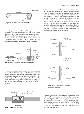
Carriage Magnetic Scale
Stainless Steel Bar
Figure 15-28 shows a typical LVDT. It consists of three
coils wound on a common form with a moving core through
the center. Applying an AC input voltage will produce an out-
put voltage that corresponds to the position of the core.
ON/OFF ZERO INCH/MM Applying a DC voltage to the input will allow the LVDT to be
Readout used as a vibration sensor. As the core moves, a magnetic field
w/ Controls is induced by the primary coil and, in turn, generates a volt-
Figure 15-26 Magnetic Scale age in the secondary coils.