
Page 289 - Electromechanical Devices and Components Illustrated Sourcebook
P. 289
Chapter 15 Sensors 251
A Hall effect sensor takes advantage of the characteristic Terminals
of some materials to change resistance when placed in a mag-
net field. These types of sensors are very inexpensive and, LED Housing Transistor Housing
consequently, very common. Figure 15-6 shows a Hall effect
Reflective Surface
sensor schematic. Like the inductive sensor, these sensors are
also commonly used in automobile distributors.
Reflective
LED Housing
Permanent Magnet
Light Chopper
Hall Trigger Circuit
Sensor Amplifier
Terminals
Output
Transistor Housing
S N
Interruption
Pole
Faces
LED Housing Transistor Housing
R 1
Terminals
Battery
Opto-Isolator
Figure 15-6 Hall Effect Proximity Sensor Schematic
Figure 15-8 Opto-Coupled Sensors
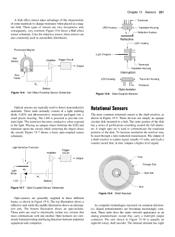
Optical sensors are typically used to detect nonconductive Rotational Sensors
materials. These units normally consist of a light emitting
diode (LED) and photosensitive transistor packaged into a The most common rotational sensor is the shaft resolver, as
small plastic housing. The LED is powered to provide con- shown in Figure 15-9. These devices are simply an opaque
stant light. The transistor becomes conductive when exposed circular disk mounted to a hub. The outer portion of the disk
to the light. Placing an opaque object between the LED and has a series of perforations extending around the full diame-
transistor opens the circuit, while removing the object closes ter. A single opto set is used to communicate the rotational
the circuit. Figure 15-7 shows a basic opto-coupled sensor position of the disk. To increase resolution the resolver may
schematic. be used through a ratio reduction transmission. The output of
a shaft resolver is a pulse signal, usually +5 volts, and feeds a
counter circuit that, in turn, outputs a higher level signal.
Light Sensitive Transistor
Trigger
Amplifier Circuit
Disk
Output
Through Slot
Light
Block Opto Set
R 1
LED Battery
Figure 15-7 Opto-Coupled Sensor Schematic Axle
Figure 15-9 Shaft Resolver
Opto-sensors are generally supplied in three different
forms, as shown in Figure 15-8. The top illustration shows a
reflective unit while the middle illustration shows an interrup- As computer technologies encroach on common electron-
tion unit. The bottom illustration shows an opto-isolator. ics, digital potentiometers are becoming increasingly com-
These units are used to electrically isolate two circuits that mon. These units have the same outward appearance as an
must communicate with one another. Opto-isolators are com- analog potentiometer, except they carry a multi-pin output
monly found providing interfacing functions between industrial connector. The unit shown in Figure 15-10 is actually an
equipment and computers. eight-bit rotary shaft encoder. The internal element has eight