
Page 284 - Electromechanical Devices and Components Illustrated Sourcebook
P. 284
246 Electromechanical Devices & Components Illustrated Sourcebook
−
Grid
Mid Voltage
No Grid +
Supply
Neutral
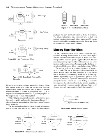
Miniature Subminiature Ultraminiature
Figure 14-12 Miniature Vacuum Tubes
−
Grid Low Voltage
−
− Grid + packages that were commonly supplied during these times.
Supply
+ The ultraminiature tubes were principally used in high-cost
test instruments, avionics, and military equipment. Of course,
Suppression
the advent of solid-state electronics spelled the certain death
of vacuum tubes in everyday appliances.
−
Grid High Voltage
+ Mercury Vapor Rectifiers
+ Grid +
Supply − The early part of the 1900s saw a variety of mercury vapor
rectifiers. By using mercury vapor in the tube, much higher
Acceleration
currents could be used and these types of diodes were com-
Figure 14-9 Grid Function and Effect
monly used for industrial power supplies. However, the only
remaining mercury vapor rectifier still in common use is the
ignitron, and even these have been principally displaced by
the advent of high-power silicon controlled rectifiers (SCRs).
V The ignitron is simply an envelope with a pool of mercury
Input Output as its cathode. The top of the envelope is equipped with an
anode. A small needle electrode, or igniter, is located on the
T 1 T 2
B side of the envelope and touching the surface of the mercury.
Figure 14-10 Basic Single Tube Amplifier When a high-voltage signal is applied to the igniter, a small
Schematic amount of mercury is vaporized. The vaporized mercury is
enough to short the cathode and anode. As long as current is
flowing across the cathode and anode, the mercury maintains a
higher voltage, which is, in turn, used to bias the grid. As the vapor state and a low resistance junction is formed. Figure 14-13
bias voltage on the grid varies, the electron flow from the shows a schematic representation of an ignitron rectifier.
cathode to the anode is controlled and the output of the tube
mirrors the input at a much higher power level. T is an
2
impedance matching transformer and is generally required on
the output of any vacuum tube amplifier.
Anode
Tubes with grids are generally classified as triodes (one grid),
tetrodes (two grids), and pentodes (three grids). Figure 14-11 Ignitor
shows schematic representations of the three types of vacuum Cathode (Mercury Pool)
tubes with grids.
The 50s and 60s brought about the systematic miniaturiza-
tion of vacuum tubes. Figure 14-12 shows the three standard Figure 14-13 Ignitron Rectifier Symbol
Anode Anode Anode
G G 3
Grid G 2 1 G 2
G 1
Cathode Cathode
Cathode
Filament Filament
Filament
Triode Tetrode Pentode
Figure 14-11 Standard Vacuum Tube Types