
Page 279 - Electromechanical Devices and Components Illustrated Sourcebook
P. 279
Chapter 13 Meters 241
Vertical Controls
Horizontal
Controls
Display (CRT) Trigger
Controls
TRIGGER
DC
AC EXT
POSITION POSITION
VOLTS/DIV SEC/DIV
COUPLING
5C .1 .2 1 .5 .1
2C .5 5 2 ms 20 10 INT LINE EXT
1C CAL 1 10 5
50 2 20 CAL us 2
1 1
20 5
s
10
2 .5
AC DC 5 XY .1 .2
SOURCE
GND
0
_
+
500 VAC MAX. HOR EXT
INTENSITY FOCUS BEAM FIND POWER INPUT INPUT LEVEL
Display Controls
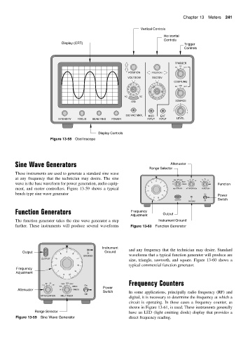
Figure 13-58 Oscilloscope
Sine Wave Generators Attenuator
Range Selector
These instruments are used to generate a standard sine wave
at any frequency that the technician may desire. The sine .50 .25
5 6 10X 100X 1KX 10KX 1MEGX 1.0 .10
wave is the base waveform for power generation, audio equip- 4 1X 10MEGX Function
3 7
ment, and motor controllers. Figure 13-59 shows a typical MULTIPLIER ATTENUATION FUNCTION
2 8
bench type sine wave generator On
Power
1
9
Switch
0
10
OUTPUT Off
GROUND
Function Generators Frequency
Adjustment Output
The function generator takes the sine wave generator a step Instrument Ground
further. These instruments will produce several waveforms Figure 13-60 Function Generator
Instrument
Output 5 Ground and any frequency that the technician may desire. Standard
4 6
GROUND waveforms that a typical function generator will produce are
OUTPUT 3 7
sine, triangle, sawtooth, and square. Figure 13-60 shows a
typical commercial function generator.
2
8
Frequency
Adjustment 1 0 10 9
.50 .25 100X 1KX 10KX Frequency Counters
1.0 .10 On
10X 1MEGX Power
Attenuator 1X 10MEGX
Switch In some applications, principally radio frequency (RF) and
Off
ATTENUATION MULTIPLIER
digital, it is necessary to determine the frequency at which a
circuit is operating. In these cases a frequency counter, as
shown in Figure 13-61, is used. These instruments generally
Range Selector have an LED (light emitting diode) display that provides a
Figure 13-59 Sine Wave Generator direct frequency reading.