
Page 283 - Electromechanical Devices and Components Illustrated Sourcebook
P. 283
Chapter 14 Vacuum Tubes 245
arrangement the cathode is indirectly heated by the filament.
The emission surface of the cathode plate is generally coated
with a material that will improve electron emission. Notice
that the filament and its supply are electrically isolated from the
meter circuit. Glass Tube
Figure 14-5 shows a half-wave DC power supply using one
vacuum tube diode. The transformer has a dual secondary,
one dedicated to the filament supply and one for the output.
The output of the tube will be pulsed DC and therefore a fil- Octal Base
ter network, made from two capacitors and a choke, is usually
required.
Octal Socket
Filter Network
Figure 14-7 Vacuum Tube with Octal Base
DC Output
Grids
Vacuum Tube Diode
AC Input A perforated plate or screen placed between the cathode and
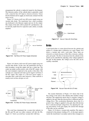
anode of a vacuum tube is referred to as a grid. Figure 14-8
Filament Supply
shows a vacuum tube with a grid plate. These units are
Transformer referred to as triodes because of their three elements, cathode,
Figure 14-5 Half-Wave DC Power Supply Schematic grid, and anode. The flow of electrons from the cathode to the
anode can be controlled by adjusting a bias voltage applied to
the grid. In this manner, the voltage across the tube can be
variably controlled.
Figure 14-6 shows a full-wave DC power supply using two
vacuum tube diodes. In this case, the transformer also has a
dual secondary, except the output side has a center tap. The
center tap makes up the positive side of the DC output, with
the outer terminals connected to the anodes of the tubes. The
cathodes are connected and make up the negative terminal of Anode
the DC output. The output of a full-wave power supply is Grid
smoother than a half-wave unit; however, a filter network is
usually used on these designs as well. Cathode
Filament
Vacuum Tube Figure 14-8 Vacuum Tube with Grid (Triode)
Diode
+ DC −
Output
AC Input The neutral illustration of Figure 14-9 shows that if the
bias voltage is the same as the cathode, then medium voltage
will flow. The suppression shows that if a negative voltage is
Filament Supply
applied to the grid, then the electron flow is deflected and low
Transformer
voltage flows. The acceleration illustration shows that if a
Figure 14-6 Full-Wave DC Power Supply Schematic positive bias voltage is applied to the grid, then full electron
flow is realized and high voltage flows. By adjusting the volt-
age and polarity of the grid supply, the current flow through
of the tube can be controlled.
The octal base dominated the vacuum tube industry in Figure 14-10 shows a vacuum tube amplifier. The input is
the 40s and 50s and was rather common well into the 60s. connected to the primary winding of T . As the input signal is
1
Figure 14-7 shows an octal base vacuum tube with base. varied, the transformer’s secondary mirrors these changes at a