
Page 290 - Electromechanical Devices and Components Illustrated Sourcebook
P. 290
252 Electromechanical Devices & Components Illustrated Sourcebook
Mounting Nut
Disk
Nonreflective Surface
Shaft Housing
Opto Array
Output Connector
Channels
Reflective Paint
Output Connector
Hub
Figure 15-10 Digital Potentiometer
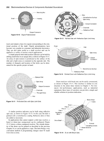
Figure 15-12 Painted Disk with Reflective Opto Limit Array
tracts and outputs a base two signal corresponding to the rota-
tional position of the shaft. Digital potentiometers have Drum Hub
become very popular in consumer and industrial electronics.
They are also quite useful as a shaft resolver and can be
applied to a variety of motion control applications. Opto Array
A simple purpose built shaft position indicator can be built by
drilling small holes in an opaque disk, as shown in Figure 15-11.
Output
An array of opto-sensors is positioned at the surface of the
Connector
disk and a light source is mounted on the opposite side. The
number of channels and location of the holes can be deter-
mined for the specific project at hand.
Nonreflective Surface
Reflective Paint
Figure 15-13 Painted Drum with Reflective Opto Limit Array
Opaque Disk
Opto Array Drum resolvers with brush sets can be easily constructed,
as shown in Figure 15-14. This resolver is similar in con-
struction to the drum timer shown in Chapter 4. For low-
Output Connector
speed, low-performance applications, such as industrial
Channels equipment, these types of encoders can provide a simple and
reliable solution to position indication.
Through Holes
Hub
Brass Strips
Figure 15-11 Perforated Disk with Opto Limit Sets Frame
Pole 4
Pole 3
Pole 2
Pole 1
A similar position indicator can be built using reflective
Insulating
opto sets, as shown in Figure 15-12. In this case the disk is Block
painted with a nonreflective coating. Reflective dots or lines
are added as necessary.
In applications that cannot support a disk-type resolver, a Drive Shaft
barrel or drum-type arrangement can be configured. Figure
Cutouts
15-13 shows a drum-configured resolver. The outside diame-
ter of the drum can be painted as described in the previous Insulating Covers
Brass Screens
Chapter 14, or can be applied as a tape. The latter being a very
Drum
convenient method if programming changes must be made
from time-to-time. Figure 15-14 Drum with Brush Sets