
Page 292 - Electromechanical Devices and Components Illustrated Sourcebook
P. 292
254 Electromechanical Devices & Components Illustrated Sourcebook
Voltmeter
1 2 3 4 5 6 7 8 9
0 10
1000
500 1500
2000 INCH Voltmeter
RPM Generator
− +
+ −
Output
Shaft
Linear Resistor
Torque
Converter
10 Inches
Induction Manual Speed
Motor Adjustment
Battery
Figure 15-22 Voltage Divider Position Indicator Schematic
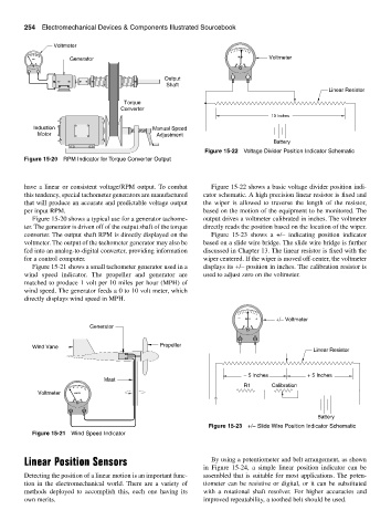
Figure 15-20 RPM Indicator for Torque Converter Output
have a linear or consistent voltage/RPM output. To combat Figure 15-22 shows a basic voltage divider position indi-
this tendency, special tachometer generators are manufactured cator schematic. A high precision linear resistor is fixed and
that will produce an accurate and predictable voltage output the wiper is allowed to traverse the length of the resistor,
per input RPM. based on the motion of the equipment to be monitored. The
Figure 15-20 shows a typical use for a generator tachome- output drives a voltmeter calibrated in inches. The voltmeter
ter. The generator is driven off of the output shaft of the torque directly reads the position based on the location of the wiper.
converter. The output shaft RPM is directly displayed on the Figure 15-23 shows a +/– indicating position indicator
voltmeter. The output of the tachometer generator may also be based on a slide wire bridge. The slide wire bridge is further
fed into an analog-to-digital converter, providing information discussed in Chapter 13. The linear resistor is fixed with the
for a control computer. wiper centered. If the wiper is moved off-center, the voltmeter
Figure 15-21 shows a small tachometer generator used in a displays its +/– position in inches. The calibration resistor is
wind speed indicator. The propeller and generator are used to adjust zero on the voltmeter.
matched to produce 1 volt per 10 miles per hour (MPH) of
wind speed. The generator feeds a 0 to 10 volt meter, which
directly displays wind speed in MPH.
4 3 2 1 1 2 3 4
5 5
− INCH + +/− Voltmeter
Generator
+ −
Propeller
Wind Vane
Linear Resistor
− 5 Inches + 5 Inches
Mast
R1 Calibration
25 50 75 100
Voltmeter KNOTS
− +
Battery
Figure 15-23 +/– Slide Wire Position Indicator Schematic
Figure 15-21 Wind Speed Indicator
Linear Position Sensors By using a potentiometer and belt arrangement, as shown
in Figure 15-24, a simple linear position indicator can be
Detecting the position of a linear motion is an important func- assembled that is suitable for most applications. The poten-
tion in the electromechanical world. There are a variety of tiometer can be resistive or digital, or it can be substituted
methods deployed to accomplish this, each one having its with a rotational shaft resolver. For higher accuracies and
own merits. improved repeatability, a toothed belt should be used.