
Page 296 - Electromechanical Devices and Components Illustrated Sourcebook
P. 296
258 Electromechanical Devices & Components Illustrated Sourcebook
Float Switches Battery
Level Indicators
Resistive Element
L
Tank L
L
Float
L
E F
Fluid
Level L
L
Voltmeter
L
Figure 15-39 Potentiometer Fluid Level
Schematic
Battery
Figure 15-37 Float Switch Level Indication
Power
Supply AC
E F
noted that the float switches can be used to control any num-
ber of electrical controls.
A potentiometer fluid level indicator, as shown in
Figure 15-38, is simply a resistive element whose wiper is Ammeter
controlled by a float. The elements are generally wire wound Fixed Plates
and configured in a semicircular pattern. The float rod is bent
so as to allow the mechanism to remain dry. The most com-
mon use of these types of lever indicators is in automobile
fuel tanks. In automotive cases, the resistive element is
Moving Core
designed to operate while immersed in the fuel.
Mount Holes
Base Plate
Wiper Terminal
Resistive Element
Float Rod Float
Float Figure 15-40 Capacitance Fluid Level Schematic
Wiper
Stop Pins
Pivot Arm
Pivot
Fluid Level
If the fluid column is sufficient, then the level can be mon-
itored using only a pressure gauge, as shown in Figure 15-41.
Figure 15-38 Potentiometer Fluid Level Indicator
This method of level indication is not particularly accurate
and is only used in applications where critical readings are not
necessary. This type of fluid level monitoring is principally
used in municipal water towers. The water utility measures
Figure 15-39 shows a typical voltage divider schematic, the system pressure and can calculate the level in the tower at
commonly used with potentiometer fluid level indicators. any given time.
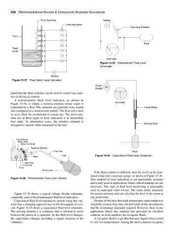
Capacitance fluid level transducers operate using the vari- Despite all the buzz that high-temperature superconductors
ation that a changing capacitor has on the throughput of a cir- originally created, they have not delivered on the speculations
cuit. Figure 15-40 shows a capacitance fluid level schematic. that the technology originally inspired. However, there is one
The moving element is a conductor that is allowed to move application where this material has provided an excellent
between the plates of a capacitor. As the fluid level changes, solution, as level monitors for cryogenic fluids.
the capacitance changes providing a signal variation to the A cryogenic fluid is a gas that becomes liquid when cooled
voltmeter. to very low temperatures. Among the most common cryogenic