
Page 301 - Electromechanical Devices and Components Illustrated Sourcebook
P. 301
Chapter 15 Sensors 263
Microammeter Collector Terminal
Envelope
Glass Envelope
Filament
Grid
Gas Input
Collector
Collector
Grid Bias Filament
Grid Supply Tubulation
Grid Terminals
Filament Filament Bias
Supply Supply
Filament Terminals
Figure 15-58 Ionization Vacuum Gauge Schematic
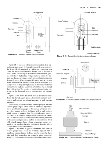
Figure 15-59 Bayard-Alpert Ionization Vacuum Gauge
Microammeter
Figure 15-58 shows a schematic representation of an ion-
ization vacuum gauge. An ionization gauge is a vacuum tube
that is specifically designed to collect and concentrate gas Envelope
atoms and molecules (particles). In this case, a filament is
heated and a bias voltage is placed across the filament, grid, Permanent Magnet
and collector. A higher bias voltage is placed across the fila-
ment and the grid, creating a steady stream of electrons across
Collector
the two elements. When a gas particle drifts into the electron High-Voltage
field it is ionized, that is to say that the particle is charged. The Emitters Supply
charged state of the particle propels it to the collector and the
microammeter reads the additional current flow that is created
during this action. The number of particles impacting the col-
lector can be displayed on the microammeter as pressure
units.
Figure 15-59 shows the most popular ionization trans-
ducer, the Bayard-Alpert gauge. These units are fairly inex- Gas Input
pensive and provide exceptional accuracy at high vacuum Figure 15-60 Cold Cathode Ionization Vacuum Gauge Schematic
pressures.
The other type of common high vacuum gauge is the cold
cathode gauge. Figure 15-60 shows a schematic representa-
tion of a cold cathode gauge. In this case, a cylindrical emit- SHV Connector
ter with a central collector is biased with a high voltage,
which creates an electron flow. As a particle drifts into the Grounded Shield
electron field, it becomes charged and is drawn to the collec- Envelope
tor. The microammeter reads the additional current generated
by this action and provides a readout in pressure units. Most
cold cathode gauges have a large permanent magnet sur- Magnet
rounding the envelope in order to improve focusing of the
charged particles onto the collector.
Figure 15-61 shows a typical commercial cold cathode
vacuum gauge head. These are normally supplied with a Gas Input
metal seal vacuum flange. It should also be noted that these
Vacuum Flange
units and their controllers are generally rather expensive,
being 5 to 10 times as costly as their ionization counterparts. Figure 15-61 Commercial Cold Cathode Vacuum Gauge