Page 305 - Electromechanical Devices and Components Illustrated Sourcebook
P. 305

Chapter 15  Sensors 267

                                  Voltmeter                    Clamp Screw
                                                  .3 .4 .5  .6  .7
                                                 .1 .2  .8 .9
                                                       1
                                                  DC VOLTS
                                                              Potentiometer                Terminals
                           Full Wave Bridge
                                                                                                       79°: 3.00 G
                                                −     +
                                                                 Lever Arm
                                                                                                      67°: 2.00 G
                                              −                                                     56°: 1.50 G
                                                               Dead Weight
                                              +
                                                                                                 45°: 1.00 G
                                                                                             33.75°: 0.75 G
                                                                                          22.5°: 0.50 G
                  Vibration Sensor       Filter Capacitor                             11.5°: 0.25 G
                                                                                 0°: 0.00 G
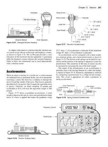
        Figure 15-75 Averaged Vibration Reading
                                                              Figure 15-77 Pendulum Accelerometer


           If a higher order analysis is desired, then the vibration sen-  22.5 , then a  / 2 -G acceleration is indicated. If the pendulum
                                                                         1
        sor can be set up with an oscilloscope and frequency counter,  swings 45 , then a 1-G acceleration is indicated.
        as shown in Figure 5-76. The oscilloscope provides a clear  An accelerometer can be configured with a dead weight,
        indication of the waveform that the equipment is generating  two centering springs, and a linear potentiometer, as shown in
        while the frequency counter indicates the resonant frequency.  Figure 15-78. The tension on the springs can be tuned for sen-
        Either of these two instruments can be used independently  sitivity and the position of the springs is adjusted to center the
        with a vibration sensor.                              potentiometer. The sensitivity of this type of sensor can also
                                                              be increased by increasing the size of the dead weight.
                                                                 The output of the potentiometer in an accelerometer is
        Accelerometers                                        generally used as the moving element of a slide wire bridge,
                                                              as shown in Figure 15-79. Sensitivity adjustment is achieved
        When an object is moving in a circular arc, a certain amount  by configuring a potentiometer in a voltage divider arrange-
        of centrifugal force is generated. In the case of an automobile  ment.  This circuit is appropriate for either a pendulum or
        traversing a corner, this force has a tendency to through the  spring accelerometer.
        driver toward the outside of the curve. This force is generally
        described in G, for gravity. One G equals the equivalent force
        of gravity.  Therefore, an object weighing 10 pounds and      Linear Potentiometer     Dead Weight
                                                                 Left Hand Spring
        accelerated at 20 G will have the equivalent weight of 200                                  Right Hand Spring
                                                               Centering
        pounds.                                                Screws
           Figure 15-77 shows a pendulum accelerometer. A dead
        weight is placed at the end of a lever arm and allowed to hang  Base
        down. If a force is applied that makes the pendulum swing  Figure 15-78 Spring Centered Accelerometer


                                                                                            100K  1Meg
                                                                                           1K  20 Meg  On
                                                 Frequency Counter
                                                                                                INPUT  Off
                                                                                            RANGE

                                                                                                        TRIGGER
                                                Oscilloscope                                            AC  DC  EXT
                                                                                         POSITION  POSITION
                                                                                        VOLTS/DIV  SEC/DIV
                                                                                                        COUPLING
                                                                                         2C 5C .1 .2  .5  5 2 1 ms  .5  .1 20  10 5  INT  LINE  EXT
                                                                                         50 1C  CAL  2  1  10  CAL  us  2
                                                                                          10 20  5  2 1 20  s  1
                                                                                       AC   DC      .5 .2
                                                                                                 XY 5  .1
                                                                                                        SOURCE
                                                                                         GND
                                                                                                         0
                                                                                                           +
                                                                                        500 V  HOR  EXT  _
                                                                  INTENSITY  FOCUS  BEAM FIND  POWER  INPUT  INPUT  LEVEL
                     Vibration Sensor
         Figure 15-76 Vibration Analysis Setup
   300   301   302   303   304   305   306   307   308   309   310