
Page 302 - Electromechanical Devices and Components Illustrated Sourcebook
P. 302
264 Electromechanical Devices & Components Illustrated Sourcebook
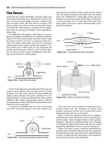
Flow Sensors paddle wheel, except that the wheel is replaced with a turbine
rotor. The number and pitch of the blades allows the turbine
Sensing the flow of gases and fluids is critical for many com- rotor to be configured for a broad range of flow rates and,
mercial and industrial processes. Sensing flow can be as sim- therefore, is a much more popular design. Figure 15-64 shows
ple as viewing a pressure gauge. If pressure is present at one a stylized sectional view of a pulse generating turbine flow
end of an open conduit, then flow must be occurring. If the meter. Figure 15-65 shows a typical commercial pulse gener-
pressure changes, then there will be a corresponding change ating flow transducer.
in the flow rate. This method is commonly used for applica-
tions where low accuracy is acceptable, such as pumping irri-
gation water. Output
For applications that require a high degree of accuracy, Sensor
there are a number of methods that are commonly employed.
Figure 15-62 shows a basic paddle wheel flow meter. A pad-
dle wheel is placed in the flow of a liquid and allowed to Flow
rotate. The output of the paddle wheel drives a tachometer
generator that, in turn, outputs a proportional signal to a volt- Flow Cowling
meter. These types of flow meters are very inexpensive and Turbine Rotor
provide good performance. Because of the generator drive, Support Spiders
they do create a certain amount of backpressure and, there- Figure 15-64 Pulse Generating Turbine Flow Meter
fore, restrict the flow to a certain degree.
Connector
Generator Voltmeter
Signal Output
Drive Belt Sensor Housing
Paddle Wheel
Flow
Figure 15-62 Paddle Wheel Flow Meter
To limit the backpressure of a paddle wheel flow meter, the
generator can be replaced with a proximity sensor, as shown
Turbine Housing
in Figure 15-63. The sensor detects the passing paddle and
Standard Pipe Flanges
outputs a pulse each time. The sensor is interfaced to a con-
troller that drives a voltmeter calibrated in flow units. Another Figure 15-65 Commercial Turbine Flow Meter
attribute to flow meters with proximity sensors is that the
moving element is sealed within the housing and there are no
rotational seals to create leaks.
A variation of the paddle wheel flow meter is the turbine One of the most common methods for measuring flow is
unit. These transducers operate in the same manner as the through pressure drop. By measuring the pressure drop
through a restriction, the flow rate of a given fluid can be
determined with a high degree of accuracy.
Figure 15-66 shows a stylized sectional view of a differen-
Output
tial pressure flow meter. The fluid is forced to flow through a
restrictor orifice, which is bridged with two resistive pressure
Sensor
transducers. The pressure transducers make up two elements
of a Wheatstone bridge and the meter reads only the voltage
generated by differential resistance of the two transducers.
Paddle Wheel Figure 15-67 shows a typical commercial differential pres-
sure flow meter and readout. These units are often constructed
by sandwiching an orifice plate between two standard flanges,
Flow
as shown. To change the flow characteristics of the transducer,
Figure 15-63 Pulse Generating Paddle Wheel Flow Meter one only needs to swap out the orifice plate.