Page 298 - Electromechanical Devices and Components Illustrated Sourcebook
P. 298

260 Electromechanical Devices & Components Illustrated Sourcebook

                     Fixed Pivot                              which also drives the gauge needle. As pressure is applied to
                                                  Terminals   the unit, the Borden tube tries to straighten out and activates
           Pressure                                           the gear mechanism that turns the needle and potentiometer.
           Housing
                                               Resistive      The output of the potentiometer can drive either a voltage
                                               Element        divider or a Wheatstone bridge.
                                              Lever Arm          For more sensitive pressure readings, a bellows pressure
        Pressure                                              transducer is generally specified, as shown in Figure 15-48.
          Port                                 Wiper
                                                              Pressure is fed to the input and the bellows extends.  The
                                                              opposite end of the bellows is connected to a linear poten-
                                     Cam                      tiometer. As the pressure varies, so does the bellow’s length
                                                              and the position of the potentiometer. The output of the poten-
                                    Diaphragm
                                                              tiometer can drive either a voltage divider or a Wheatstone
        Figure 15-45 Diaphragm Pressure Transducer            bridge.


                            Potentiometer
                        Gauge Housing      Terminals                   Bellows                Plunger Rod
                                                                                                    Linear
                                                                 Input Head
                                                                                                    Potentiometer
                                                                Pressure
          Needle    80  100 120
                   60   140                                      Input
          Bezel    40   160
                   20   180                                      Bellows Weld
                     PSI  200                    A  B  C                                      Terminals
                                                                                           Moving Head
                     USA
                                                                Figure 15-48 Bellows Pressure Transducer
         NPT Thread
                Input
         Figure 15-46 Commercial Pressure Gauge with 0- to 10-Volt
         Output
                                                                 A bellows-type pressure transducer can be constructed
                                                              using a spring return cylinder, as shown in Figure 15-49. The
                                                              output shaft of the cylinder is connected to the shaft of a lin-
           Pressure transducers are also available in a pressure gauge  ear potentiometer with a connecting nut. A cylinder arrange-
        package, as shown in Figure 15-46. These units have princi-  ment will not be as sensitive to minute changes as a bellows
        pally the same appearance as a standard pressure gauge,  because the piston and cylinder will exhibit a certain amount
        except that they have an extended rear housing and three ter-  of stiction.
        minals. The rear housing accommodates a potentiometer ele-
        ment. Information supplied by the manufacturer should be
        used for wiring the transducer, although the center terminal is
                                                                             Cylinder Rod
        generally the wiper.                                       Spring Return                Plunger Rod
                                                                     Cylinder                        Linear
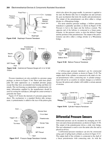
           Figure 15-47 shows the internals of a pressure gauge trans-                               Potentiometer
        ducer.  The mechanism is a standard Borden tube arrange-
        ment. A potentiometer is added to the rear of the pinion gear,
                                                                                                Terminals
                                                                           Pressure Input
                                                                                            Connector Nut
                                                                                  Jam Nuts
                                                                Figure 15-49 Cylinder Pressure Transducer
                  Case
                                           Circular Rack
                                             Pinion Gear
                                                              Differential Pressure Sensors
            Toggle Link
                                             Potentiometer
                 Face                                         Differential pressure can be measured by arranging two bel-
                Terminals                    Borden Tube      lows sets and a linear potentiometer, as shown in Figure 15-50.
                                                              The output of the potentiometer drives a slide wire bridge.
                                         Solder Joint         The zero adjustment is used to zero the meter after the unit is
                                                              placed in service.
                                                                 A differential pressure transducer can also be constructed
                                        NPT Thread
                                                              using a pair of spring return cylinders, as shown in Figure 15-51.
                                    Input                     The output shaft of the cylinders is connected to the shaft of
            Figure 15-47 Pressure Gauge Transducer Internals  a linear potentiometer with connecting nuts.  As with the
   293   294   295   296   297   298   299   300   301   302   303