
Page 303 - Electromechanical Devices and Components Illustrated Sourcebook
P. 303
Chapter 15 Sensors 265
Voltmeter Calibration Compensator Resistor
Voltmeter
Power
Supply
Pressure Transducers
Battery
Gauge Element
Flow
Flow
Figure 15-68 Hot Wire Flow Meter
Orifice
Flange Set
Figure 15-66 Differential Pressure Flow Meter
Battery
P1
RESET
P2 Voltmeter
CAL.
Readout Resistive Element
Pressure Transducers
Flow
Flow
Paddle
Figure 15-69 Paddle Flow Meter
Standard Pipe
Orifice Plate Flanges
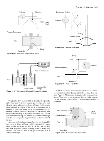
Figure 15-67 Commercial Differential Pressure Flow Meter Paddle flow sensors are most commonly found in automo-
tive applications where they are referred to as mass flow sen-
sors. Figure 15-70 shows a typical automotive style mass flow
sensor. These units gauge the air flow that the engine is draw-
ing and matches the fuel delivery rate to achieve maximum
Gauging the flow of gas is little more difficult, especially efficiency.
at low flow rates. To achieve accurate gas flow rates a hot wire
element is generally used, as shown in Figure 15-68. An ele-
ment is placed in the flow of the gas to be measured and is
heated to a fixed level. As the rate of the gas flowing over the
Data Connector
element increases, it has a cooling effect on the element with Paddle
its resistance lowering in proportion to the flow rate. The hot Housing
wire element makes up one element of a Wheatstone bridge Encoder Housing
with the out voltage directly proportional to the flow rate of
the gas.
A second method of gauging gas flow rate is with a paddle Flow
flow meter, as shown in Figure 15-69. In this method, a trans-
ducer paddle interrupts the flow of the gas. As the flow
increases, the paddle deflects actuating the wiper on a poten-
tiometer. The unit can drive a voltage divider circuit or a Hose Barb
Wheatstone bridge. Figure 15-70 Automotive Mass Flow Sensor