
Page 308 - Electromechanical Devices and Components Illustrated Sourcebook
P. 308
270 Electromechanical Devices & Components Illustrated Sourcebook
measure the time it takes for a known weight to fall through a
column of liquid. The set up shown uses a graduated cylinder Force
placed on an ordinary laboratory stand. A weighted rod with
a paddle on one end is suspended in the center of the cylinder.
The rod is pulled up and held in place by a solenoid-operated
brake assembly. The solenoid and a limit switch communicate
Steel Frame
with an ordinary laboratory timer. When the start button on
the timer is pressed, the solenoid releases the brake and the rod
Strain Gauge Element
starts to fall at the same instant the timer starts. When the rod
reaches the bottom, it trips the limit switch, which turns off
the timer. By gauging the displayed time, the viscosity of the
fluid can be determined.
Load Cells
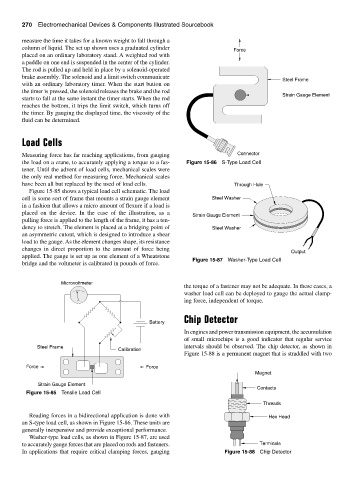
Measuring force has far reaching applications, from gauging Connector
the load on a crane, to accurately applying a torque to a fas- Figure 15-86 S-Type Load Cell
tener. Until the advent of load cells, mechanical scales were
the only real method for measuring force. Mechanical scales
have been all but replaced by the used of load cells. Through Hole
Figure 15-85 shows a typical load cell schematic. The load
cell is some sort of frame that mounts a strain gauge element Steel Washer
in a fashion that allows a micro amount of flexure if a load is
placed on the device. In the case of the illustration, as a
Strain Gauge Element
pulling force is applied to the length of the frame, it has a ten-
dency to stretch. The element is placed at a bridging point of Steel Washer
an asymmetric cutout, which is designed to introduce a shear
load to the gauge. As the element changes shape, its resistance
changes in direct proportion to the amount of force being
Output
applied. The gauge is set up as one element of a Wheatstone
Figure 15-87 Washer-Type Load Cell
bridge and the voltmeter is calibrated in pounds of force.
Microvoltmeter
the torque of a fastener may not be adequate. In these cases, a
washer load cell can be deployed to gauge the actual clamp-
ing force, independent of torque.
Chip Detector
Battery
In engines and power transmission equipment, the accumulation
of small microchips is a good indicator that regular service
Steel Frame intervals should be observed. The chip detector, as shown in
Calibration
Figure 15-88 is a permanent magnet that is straddled with two
Force Force
Magnet
Strain Gauge Element
Contacts
Figure 15-85 Tensile Load Cell
Threads
Reading forces in a bidirectional application is done with Hex Head
an S-type load cell, as shown in Figure 15-86. These units are
generally inexpensive and provide exceptional performance.
Washer-type load cells, as shown in Figure 15-87, are used
to accurately gauge forces that are placed on rods and fasteners. Terminals
In applications that require critical clamping forces, gauging Figure 15-88 Chip Detector