
Page 309 - Electromechanical Devices and Components Illustrated Sourcebook
P. 309
Chapter 15 Sensors 271
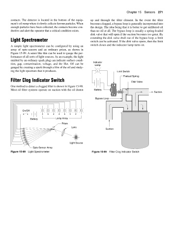
contacts. The detector is located in the bottom of the equip- up and through the filter element. In the event the filter
ment’s oil sump where it slowly collects ferrous particles. When becomes clogged, a bypass loop is generally incorporated into
enough particles have been collected, the contacts become con- the design. The idea being that it is better to get unfiltered oil
ductive and alert the operator that a critical condition exists. than no oil at all. The bypass loop is usually a spring-loaded
disk valve that will open if the suction becomes too great. By
extending the disk valve shaft out of the bypass loop, a limit
Light Spectrometer switch can be activated. If the disk valve opens, then the limit
A simple light spectrometer can be configured by using an switch closes and the indicator lamp turns on.
array of opto-sensors and an ordinary prism, as shown in
Figure 15-89. A senor like this can be used to gauge the per-
formance of all sorts of light sources. As an example, the light
emitted by an ordinary spark plug can indicate surface condi-
Indicator
tion, gap, contamination, voltage, and the like. Oil can be
Lamp
gauged by creating a spark through a film of the oil and study-
ing the light spectrum that it produces. L Limit Switch
Preload Spring
Filter Clog Indicator Switch Disk Valve
One method to detect a clogged filter is shown in Figure 15-90. NC
Most oil filter systems operate on suction with the oil drawn Battery COM
Suction
NO
Bypass Loop
On/Off L L L L L L L L
Battery Lamp Array
Prism
Lens
Suction
Light Source
Opto-Sensor Array
Figure 15-89 Light Spectrometer Figure 15-90 Filter Clog Indicator Switch