Page 264 - Electromechanical Devices and Components Illustrated Sourcebook
P. 264

226 Electromechanical Devices & Components Illustrated Sourcebook

                                                                   Multiply
                                                                 Reading by 10
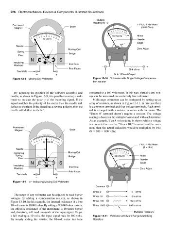
          Permanent                              Scale                                         10 Volt, 1 Ma Meter
           Magnet                                                                                 (10 K Ohm)
                                                                            1 2 3  4  5 6 7 8 9
                                                                                       10
                                                                              DC VOLTS         Mirror
                              DC VOLTS                                                         Needle
                          1 2 3 4 5 6 7 8 9 10
                                                                                               Stops
            Needle
                                                Moving Coil                                    Zero Adjust
             Spring
                                                Bridge                      −         +
              Pivot
                      N                   S
          Insulating                            Iron Core
           Washers                                                     −                             +
                                                Pole Faces                               90 k ohms
             Terminals
                          −            +                                       0- to 100-volt Output
          Figure 13-8 Moving Coil Voltmeter                      Figure 13-10 Voltmeter with Single Voltage Compensa-
                                                                 tion resistor


           By adjusting the position of the coil/core assembly and  converted to a 100-volt meter. In this way, virtually any volt-
        needle, as shown in Figure 13-9, it is possible to set up a volt-  age can be measured on a relatively low voltmeter.
        meter to indicate the polarity of the incoming signal. If the  Multirange voltmeters can be configured by setting up an
        signal matches the polarity of the meter then the needle will  array of resistors, as shown in Figure 13-11. In this case there
        deflect to the right. If the signal has a reverse polarity, then the  is a common terminal and four voltage terminals. Each termi-
        needle will deflect to the left.                       nal is arranged with a resistor in series with the meter. The
                                                              “Times 0” terminal doesn’t require a resistor.  The voltage
                                                              reading is based on the multiplier associated with each terminal.
                                                              As an example, if an 8-volt reading is shown while a voltage
                                                              is connected across the “Times 100” terminal and the com-
          Permanent                                           mon, then the actual indication would be multiplied by 100.
           Magnet                                Scale
                                                              (8   100   800 volts)
                          4 3 2 1  1 2 3 4
                        − 5    DC    VOLTS  5 +                                                 1 Volt, 1 Ma Meter
                                                                                                   (1 k ohm)
            Needle                                                               4
          Centering                             Moving Coil                   1 2 3  5 6 7 8 9  10
            Spring                              Bridge                          DC VOLTS         Mirror
              Pivot
                                                                                                 Needle
                      N                   S                                                      Stops
          Insulating                            Iron Core
           Washers                                                                               Zero Adjust
                                                Pole Faces
             Terminals                                                       −         +
                         −             +

          Figure 13-9 +/– Indicating Moving Coil Voltmeter
                                                                   Common

                                                                 Times 0                   0    ohms
           The range of any voltmeter can be adjusted to read higher
                                                                 Times 10                  9 k ohms
        voltages by adding a compensation resistor, as shown in
        Figure 13-10. In this example, the internal resistance of a 0 to  Times 100       99 k ohms
        10 volt meter is 10,000  ohm. By adding a 900,000-ohm resistor,  Times 1000       999 k ohms
        the effective resistance of the instrument is 10 times higher
        and, therefore, will read one-tenth of the input signal. To get                      Multiplier Resistors
        a full reading at 10 volts, the input signal must be 100 volts.  Figure 13-11 Voltmeter with Multi Range Multiplying
        By simply adding the resistor, the 10-volt meter has been  Resistors
   259   260   261   262   263   264   265   266   267   268   269