
Page 266 - Electromechanical Devices and Components Illustrated Sourcebook
P. 266
228 Electromechanical Devices & Components Illustrated Sourcebook
1 2 3 4 5 6 7 8 9 .1 .2 .3 .4 .5 .6 .7 .8 .9
10 2 3 4 1
1 5 6 7 8 9 10
DC AMPS 0 to 10 volt, DC AMPS 1 volt, 10 mA
1 mA Meter
(10 k ohms) (100 ohm)
− + − +
1 amp 1 ohm
Power Shunt Resistor +
Supply 1 ohm, 10 watt Load −
10 amp 10 ohm
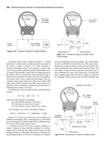
Figure 13-16 Voltmeter Configured to Indicate Amperes
Range Selector Shunt Resistors
Figure 13-17 Voltmeter Configured to Indicate Three
Current Ranges
Measuring current with a standard voltmeter is a simple set up for multirange resistance readings. The 0 ohms adjust
proposition. A shunt resistor is added across the terminals of is used to calibrate the meter before use. The range that is
the meter, as shown in Figure 13-16. The resistance is being used is connected directly to the common terminal. The
matched to the meter so that 1 volt is equal to 1 amp. In this meter will deflect to zero, but may not be exactly on zero. The
case a 1-ohm resistor is placed in parallel with the meter to act zero adjust can then be used to tune the needle precisely to
as a shunt. If the load pulls 8 amps, then the voltage drop across zero, calibrating the meter. The X100 range is actually the
the resistor will be 8 volts and the meter will read 8 amps. It direct reading range. The X10 and X1 ranges are achieved
should also be noted that the resistor selected for this applica- by switching a shunt resistor across the meter terminals and
tion must be able to carry a significant percentage of the cur-
rent that is being tested. In this case, if the circuit requires 800
watts under normal operation and 1000 watts at peak meter
deflection, then the shunt the resistor selected should have a Logarithmic ohms Scale
minimum power rating of 10 watts.
To calculate the valve of a shunt resistor, use the following OHMS
formula: 1K 500 200 100 50
5K 2K 10 0
20 30
10 40 50
R R [(D O ) 1] uA 50- _a Meter
s
s
m
s
(1.8 k ohm)
is the resistance of the shunt
where: R s
R is the internal resistance of the meter Battery
m
D is the desired current scale in amps (1.5 Volt)
s
O is the original or meter current scale in amps − + Zero ohms Adjust
s
(+/− 5 k ohm)
As an example, our circuit is calculated as follows:
[10 (D ) 0.001 (O ) 1] 10,000 (R ) 1 (R )
s
s
m
s
Unknown 23 k ohm
Figure 13-17 shows a one voltmeter set up to indicate two Resistance X100
different current ranges. The 1-amp range uses a 1-ohm shunt X10
and the 10 range uses a 10-ohm shunt. The two different ranges 300 ohm 3 k ohm
X1
are selected with a simple toggle switch.
A voltmeter can also be set up to measure resistance. A
Range Selector Switch
battery is placed in series with the resistance to be deter-
mined, and by knowing the voltage of the battery and the
internal resistance of the meter; the unknown resistance can Test Terminals
be determined. Figure 13-18 shows a schematic of a voltmeter Figure 13-18 Microammeter Configured to Measure Ohms