
Page 236 - Electromechanical Devices and Components Illustrated Sourcebook
P. 236
198 Electromechanical Devices & Components Illustrated Sourcebook
Insulating Spacer Step-Up
Metalized Diaphragm
Transformer
Rear Electrode
Front Electrode
Front Electrode
Audio Signal
Input Diaphragm
Rear Electrode
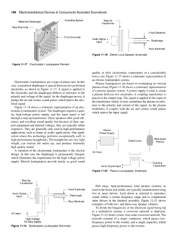
Figure 11-19 Electrit Loud Speaker Schematic
Figure 11-17 Electrostatic Loudspeaker Element
quality as their electrostatic counterparts at a considerably
lower cost. Figure 11-19 shows a schematic representation of
an electric loudspeaker system.
Electrostatic loudspeakers are a type of planar unit. In this
Plasma loudspeakers are based on modulating an ionized
case, a metalized diaphragm is spaced between two perforated
plasma cloud. Figure 11-20 shows a schematic representation
electrodes, as shown in Figure 11-17. A signal is applied to
of a plasma speaker system. A power supply is used to create
the electrodes and the diaphragm deflects in reference to the
a plasma between two electrodes. A coupling transformer is
polarity and voltage of the signal. As the diaphragm moves, it
placed in the output loop. The signal is applied to the input of
pumps the air and creates sound pulses which mirror the elec-
the transformer which, in turn, modulates the plasma in refer-
trical signal.
ence to the polarity and current of the signal. As the plasma
Figure 11-18 shows a schematic representation of an elec-
modulates, it couples with the air and creates sound pulses
trostatic Loudspeaker system. The diaphragm requires a qual-
which mirror the input signal.
ity, high-voltage power supply, and the input signal is fed
through a step-up transformer. These speakers offer good effi-
ciency and excellent sound quality but because of their sup-
port equipment and internal voltages, they are typically rather
expensive. They are generally only used in high-performance
Plasma
applications such as home or studio applications. One appli- Power Supply
cation where this technology performs exceptionally well, is
high-performance headphones. The headphones are very light Output Loop Modulated
weight, can enclose the entire ear, and produce extremely Plasma
high quality sound.
A variation of the electrostatic loudspeaker is the electric
AC Input
design. In this case the diaphragm is permanently charged,
which eliminates the requirement for the high-voltage power
supply. Electrit loudspeakers provide nearly as good sound
Coupling
Audio Signal Input Transformer
Figure 11-20 Plasma Loudspeaker Schematic
Step-Up
Transformer
Full range, high-performance loud speaker systems, as
Front Electrode used in the home and studio, are typically manufactured using
Audio Signal two or more drivers. Each driver is selected to reproduce
Input Diaphragm sound within a certain frequency range and to complement
other drivers in the finished assembly. Figure 11-21 shows
Rear Electrode
examples of both two- and three-way speaker cabinets.
To divide the frequencies of the electrical signal being fed
to a multidriver system, a crossover network is deployed.
AC Input
Figure 11-22 shows a basic first-order crossover network. The
High-Voltage network consists of a single conductor, which passes low-
DC Bias Supply frequency power to the woofer, and a single capacitor, which
Figure 11-18 Electrostatic Loudspeaker Schematic passes high-frequency power to the tweeter.