
Page 326 - Electromechanical Devices and Components Illustrated Sourcebook
P. 326
288 Electromechanical Devices & Components Illustrated Sourcebook
In the fields of electronics and electrics, the written language schematic that is actually more difficult to interpret. To further
is the schematic. A schematic is a graphical representation of confuse matters, many designers use a combination of stan-
an electronic or electrical assembly or installation. These dards ranging from international, national, industrial, military,
drawings may be as simple as a small printed label glued onto and even obsolete.
the inside of a toaster case or as complex as hundreds of engi- The thing to remember when reading or drawing a
neering drawings representing the complex power distribution schematic is for whom it is intended. If you’re a military tech-
and control systems for a petrochemical plant. Opening the nician looking at a commercial power distribution diagram,
case on an ordinary stereo will usually put you face-to-face you’re probably going to have a lot of questions. Similarly, if
with a single-sheet schematic which describes the circuitry you’re a designer tasked with drawing a schematic for a con-
with sufficient details to aid a repair technician in his task of sumer audio power amplifier kit, remember that the customer
troubleshooting. On the other hand, a modern airliner will is probably an amateur with no formal training in electronics.
have something on the order of 10 to 20, 3-inch thick binders An electrical designer that produces industrial control panels
that are nothing but electrical schematics and diagrams can easily produce a cryptic drawing that is 100% electrically
describing every aspect of the electronics and electrical systems accurate. However, do you really want the shop technicians
onboard. In addition to the circuit diagrams and schematics, deciding where to place the components, what gauge wire to
these binders will also contain test, calibration, and inspection use, and how to cable the assembly? A little quality time spent
procedures. Military ships are so complex that their printed developing a consistent drawing that is easily understandable
electrical schematics and diagrams are usually stored in a special will provide substantial returns in the future.
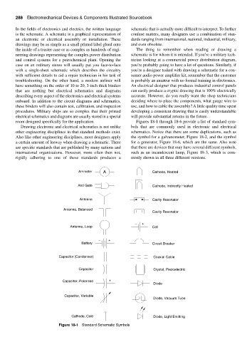
room designed specifically for the application. Figures 18-1 through 18-6 provide a list of standard sym-
Drawing electronic and electrical schematics is not unlike bols that are commonly used in electronic and electrical
other engineering disciplines in that standard methods exist. schematics. Notice that there are some duplications, such as
Also like other engineering disciplines, most designers apply the symbol for a galvanometer, Figure 18-2, and the symbol
a certain amount of leeway when drawing a schematic. There for a generator, Figure 18-6, which are the same. Also note
are specific standards that are published by many nations and that there are devices that may have several different symbols,
international organizations. However, more often then not, such as an incandescent lamp, Figure 18-3, which is com-
rigidly adhering to one of these standards produces a monly shown in all three different versions.
Ammeter A Cathode, Heated
And Gate Cathode, Indirectly Heated
Antenna Cavity Resonator
Antenna, Balanced
Cavity Resonator
− +
Antenna, Loop Cell
− +
Battery Circuit Breaker
Capacitor (Condenser) Coaxial Cable
Capacitor Crystal, Piezoelectric
Capacitor, Polarized +
Diode
Capacitor, Variable
Diode, Vacuum Tube
Cathode, Cold Diode, Light Emitting
Figure 18-1 Standard Schematic Symbols