
Page 321 - Electromechanical Devices and Components Illustrated Sourcebook
P. 321
Chapter 17 Electromechanical Mechanisms 283
240/480-VAC
Input Fuses Input
Control Transformer
Output Fuse
Buzzer
Bell 120-VAC
Receptacle
Front Door Figure 17-12 120-VAC Utility Transformer Schematic
Back Door
18-Volt
Transformer
Figure 17-12 shows a schematic representation of the util-
Side Door ity control transformer. It is important to use both input and
120 VAC output fuses , as shown.
Figure 17-10 Three Door Bell System
String Drives
three phase). In these cases, a simple utility transformer can Figure 17-13 shows a typical arrangement used in radio
be configured, as shown in Figure 17-11. A suitable control receivers to adjust the frequency with a variable capacitor. A
transformer is selected and mounted in a NEMA (National string is wrapped around a small capstan mounted on the back
Electric Manufacturers Association) cabinet along with a 120- of a knob. The string is routed around an idler and the large
VAC receptacle. Control transformers are readily available tuner pulley. Over the length of the string, a pointer is
with dual-voltage inputs and integral fuse sets. The cabinet mounted to indicate the relative frequency on the scale.
can be mounted directly onto or adjacent to the power dis- Although these types of drives are most commonly found on
connect that services the equipment. radios, they are applicable to a variety of other applications.
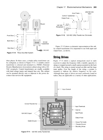
Input Conduit
Control Transformer
Input Terminals
240/480 VAC
Cabinet
120-VAC Output Input Fuses
Output Fuse
115/120 VAC
Outlet Ground
Output Terminals
Chassis Ground
Mounting Holes
Figure 17-11 120-VAC Utility Transformer