
Page 318 - Electromechanical Devices and Components Illustrated Sourcebook
P. 318
280 Electromechanical Devices & Components Illustrated Sourcebook
Electromechanical mechanisms can be extremely complex
assemblies. Consider an automobile, a clothes washer, your
computer printer, or the air conditioner, all are just big elec-
tromechanical components. Door
This chapter of the book is intended to expose the reader to Frame
a few miscellaneous electromechanical components and
Hinge
assemblies that haven’t been reviewed in the previous chapters.
Anchor Block
Strain Relief
Solenoid Door Latch
Cable
Figure 17-1 shows a simple solenoid-activated door latch. The
bolt is spring-loaded and interfaces with a striker, so the sys-
tem will automatically latch when the door is closed. To
unlock the mechanism, the solenoid is energized and the
plunger toggles the link, which, in turn, pulls the bolt back.
Figure 17-2 Hinge Cable
Fracture Groove
Door Swing Head Shank
Nut
Bolt Link
Frame Door Trigger Leads
Connecting Link
Toggle Pivot
Bolt
Charge Head
Toggle Link Striker Explosive Charge
O-Ring
Bolt Frame Mating Surfaces
Fixed Pivot of Flanges
Spring Pin
Return Spring Figure 17-3 Explosive Bolt
Solenoid Pivot
Solenoid
Solenoid Plunger
Figure 17-1 Solenoid Latch
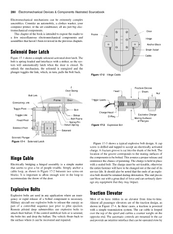
Figure 17-3 shows a typical explosive bolt design. A cap
screw is drilled and tapped to accept an electrically activated
charge. A fracture groove is cut into the shank of the bolt. The
location of the groove corresponds to the mating surfaces of
Hinge Cable the components to be bolted. This assures a proper release and
minimizes the chance of jamming. The charge is held in place
Electrically bridging a hinged assembly is a simple matter with a sealed bolt. The charge must be serviceable, otherwise
that seems to give a lot of people trouble. Simply anchor a the entire fastener will have to be changed out at the end of its
cable loop, as shown in Figure 17-2 between two screw-on service life. It should also be noted that the ends of an explo-
blocks. It is important to allow enough wire in the loop to sive bolt should be retained during detonation. The end pieces
accommodate the throw of the door. can blow out with a great deal of force and can seriously dam-
age any equipment that they may impact.
Explosive Bolts
Traction Elevator
Explosive bolts are used in any application where an emer-
gency or rapid release of a bolted component is necessary. Most of us have ridden in an elevator from time-to-time.
Military aircraft use explosive bolts to release the canopy as Almost all passenger elevators are of the traction design, as
part of a controlled sequence just prior to pilot ejection. shown in Figure 17-4. In these cases, a traction is powered
Remote piloted deep submersibles use explosive bolts to with a simple transmission system. The car cable is looped
attach their ballast. If the control umbilical fails or is severed, over the top of the spool and carries a counter weight on the
the bolts fire and drop the ballast. The vehicle floats back to opposite end. The automatic controls are mounted in the car
the surface where it can be recovered and repaired. and provide an intuitive interface that can be operated even by