
Page 315 - Electromechanical Devices and Components Illustrated Sourcebook
P. 315
Chapter 16 Electrostatics 277
Corona
5
Insulation Tester 0 1 2 20 30 3 4 40 50 60 70 6 7 8 9 10 Rounded Tip
10 80 90 100
(Megger) 0 Mega Ohms
Sharp Tip
High Low
Leakage Leakage
Insulated
Drive Shaft High High
Component to Be Floated Voltage Voltage
at High Voltage
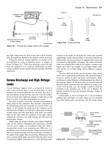
Figure 16-8 Corona Discharge
Control Panel
Figure 16-7 Verifying High-Voltage Isolation with a Megger
any high voltage that may leak to the panel will be immedi- I turned on the lights, de-energized the circuit and carefully
ately grounded and, therefore, the operator will be protected. applied high-voltage silicone rubber to all of the soldered and
Testing the stand-off voltage capability of a design can be bolted joints. The next morning I re-energized the circuit and
accomplished by using an insulation tester, or megger, as it produced its full 10,000-volt output. The solder and bolted
shown in Figure 16-7. These tests should be carried out only joints were leaking 80% of the power supply’s voltage to air!
while the equipment is de-energized. Additionally, any high- Figure 16-9 shows an example of poor high-voltage solder
voltage isolation system should undergo regularly scheduled joint and the use of high-voltage silicon rubber to suppress
inspections. leakage.
The slow build up of dirt can also produce high-voltage
leaks. This is particularly problematic with equipment that is
forced to operate in dirty and dusty environments. High-
Corona Discharge and High-Voltage performance cabinet filtration will help mitigate the effects of
dirt built-up. Figure 16-10 shows how an exposed stand off
Leaks insulator can be protected from dirt build-up by using a pro-
tective boot. In this case, the leakage would be from the
Corona discharge happens when a conductor is forced to
terminals to the grounded case. If the case is floating, the
carry more electrons than it can accommodate. In these
leakage would be between the terminals forming a bypass of
instances the electrons jump into the air where they flow to
the component.
any neutralizing charge that they may find. Near the conduc-
Carbon paths, as shown in Figure 16-11, are an insidious
tor the electrons have sufficient energies to ionize the air and
problem that will build over time. There are two principal
force it to glow, or in other terms produce a corona.
ways that carbon paths can develop. The first being during
The most common reason for electron concentration is
sharp points on the conductor. The electrons concentrate at
the diminishing point and eventually are forced off the con-
ductor. As an example, the sharp tip of the conductor on the
left hand side of Figure 16-8 will have a great deal of leakage
at high voltage and will, most likely, glow with a low purple Sharp Solder
light. On the other hand, the conductor on the right, with its Points
rounded tip, will have very little leakage and will stand off Cut Wire Ends
much higher voltages.
Solder joints are always a trouble spot in high-voltage cir- Sharp Component
Edges
cuits. In one instance I designed and constructed a 10,000-
Insufficient Spacing
volt DC power supply for an industrial flash unit. When I From Ground
energized the circuit, it was outputting only 2000 volts. As I
probed the circuit I noticed that the voltage got progressively High-Voltage Silicon
lower as I worked through from the transformer secondary to Rubber to Suppress
Leakage
the output of the supply. This was puzzling. Without any other
ideas, I turned off the lights and noticed that the entire circuit
was glowing brightly from numerous corona discharge sites. Figure 16-9 Suppressing Corona Discharge