Page 319 - Electromechanical Devices and Components Illustrated Sourcebook
P. 319

Chapter 17  Electromechanical Mechanisms 281
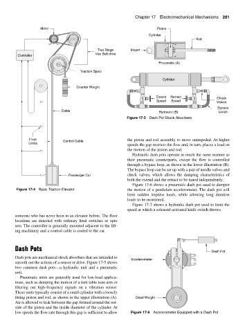
                    Motor                                                    Piston
                                                                         Cylinder
                                                                                               Rod


                                                Two Stage       Mount
                                               Vee Belt drive
          Controller
                                                                             Pneumatic (A)
                                        Traction Spool

                                                                               Cylinder
                                      Counter Weight

                                                                            Extend  Retract              Check
                                                                            Speed  Speed                 Valves
                                                                                                          Bypass
                               Cable                                          Hydraulic (B)               Loops
                                                              Figure 17-5 Dash Pot Shock Absorbers


               Floor                                          the piston and rod assembly to move unimpeded. At higher
                               Control Cable
               Limits                                         speeds the gap restricts the flow and, in turn, places a load on
                                                              the motion of the piston and rod.
                                                                 Hydraulic dash pots operate in much the same manner as
                                                              their pneumatic counterparts, except the flow is controlled
                                                              through a bypass loop, as shown in the lower illustration (B).
                                                              The bypass loop can be set up with a pair of needle valves and
                                  Passenger Car               check valves, which allows the damping characteristics of
                                                              both the extend and the retract to be tuned independently.
                                                                 Figure 17-6 shows a pneumatic dash pot used to dampen
         Figure 17-4 Basic Traction Elevator                  the motion of a pendulum accelerometer. The dash pot will
                                                              limit sudden impulse loads, while allowing long duration
                                                              loads to be monitored.
                                                                 Figure 17-7 shows a hydraulic dash pot used to limit the
                                                              speed at which a solenoid-activated knife switch throws.
        someone who has never been in an elevator before. The floor
        locations are detected with ordinary limit switches or opto
        sets. The controller is generally mounted adjacent to the lift-
        ing machinery and a control cable is routed to the car.


        Dash Pots
                                                                                                       Dash Pot
        Dash pots are mechanical shock absorbers that are intended to
                                                                Accelerometer
        smooth out the actions of a sensor or drive. Figure 17-5 shows
        two common dash pots—a hydraulic unit and a pneumatic
        unit.
           Pneumatic units are generally used for low-load applica-
        tions, such as damping the motion of a turn table tone arm or
        filtering out high-frequency signals on a vibration sensor.
        These units typically consist of a small cylinder with a loosely
        fitting piston and rod, as shown in the upper illustration (A).  Dead Weight
        Air is allowed to leak between the gap formed around the out-
        side of the piston and the inside diameter of the cylinder. At
        low speeds the flow rate through this gap is sufficient to allow  Figure 17-6 Accelerometer Equipped with a Dash Pot
   314   315   316   317   318   319   320   321   322   323   324