
Page 322 - Electromechanical Devices and Components Illustrated Sourcebook
P. 322
284 Electromechanical Devices & Components Illustrated Sourcebook
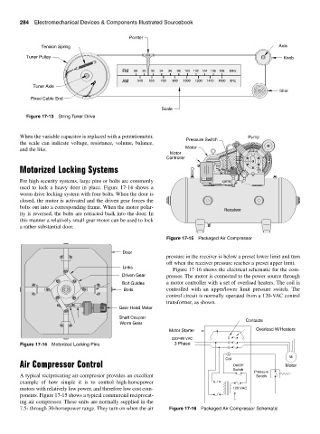
Pointer
Tension Spring Axle
Tuner Pulley Knob
FM 88 90 92 94 96 98 100 102 104 106 108 MHz
AM 540 600 700 800 1000 1200 1400 1600 kHz
Tuner Axle
Idler
Fixed Cable End
Scale
Figure 17-13 String Tuner Drive
When the variable capacitor is replaced with a potentiometer, Pump
Pressure Switch
the scale can indicate voltage, resistance, volume, balance,
and the like. Motor
Motor
Controller
Motorized Locking Systems
For high security systems, large pins or bolts are commonly
used to lock a heavy door in place. Figure 17-14 shows a
worm drive locking system with four bolts. When the door is
closed, the motor is activated and the driven gear forces the
bolts out into a corresponding frame. When the motor polar-
Receiver
ity is reversed, the bolts are retracted back into the door. In
this manner a relatively small gear motor can be used to lock
a rather substantial door.
Figure 17-15 Packaged Air Compressor
Door
pressure in the receiver is below a preset lower limit and turn
off when the receiver pressure reaches a preset upper limit.
Links
Figure 17-16 shows the electrical schematic for the com-
Driven Gear pressor. The motor is connected to the power source through
Bolt Guides a motor controller with a set of overload heaters. The coil is
Bolts controlled with an upper/lower limit pressure switch. The
control circuit is normally operated from a 120-VAC control
transformer, as shown.
Gear Head Motor
Shaft Coupler
Contacts
Worm Gear
Motor Starter Overload W/Heaters
220/480 VAC
Figure 17-14 Motorized Locking Pins 3 Phase
C
M
Coil
Air Compressor Control On/Off Motor
Switch
Pressure
A typical reciprocating air compressor provides an excellent Switch
example of how simple it is to control high-horsepower
motors with relatively low power, and therefore low cost com- 120 VAC
ponents. Figure 17-15 shows a typical commercial reciprocat-
ing air compressor. These units are normally supplied in the
7.5- through 30-horsepower range. They turn on when the air Figure 17-16 Packaged Air Compressor Schematic