
Page 320 - Electromechanical Devices and Components Illustrated Sourcebook
P. 320
282 Electromechanical Devices & Components Illustrated Sourcebook
Return Spring Power/Brake
Power/Brake Control
Switch
DC Power
Field Terminals
Link Pivot
Output
Dash Pot Resistive Shaft
Pivot Link Load Dump
Power Shaft
Terminals Coupler
Shunt Wound
DC Motor
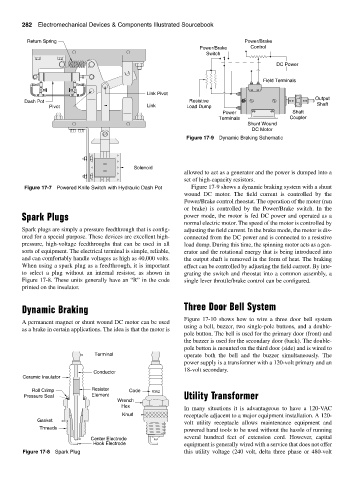
Figure 17-9 Dynamic Braking Schematic
Solenoid
allowed to act as a generator and the power is dumped into a
set of high-capacity resistors.
Figure 17-7 Powered Knife Switch with Hydraulic Dash Pot Figure 17-9 shows a dynamic braking system with a shunt
wound DC motor. The field current is controlled by the
Power/Brake control rheostat. The operation of the motor (run
or brake) is controlled by the Power/Brake switch. In the
Spark Plugs power mode, the motor is fed DC power and operated as a
normal electric motor. The speed of the motor is controlled by
Spark plugs are simply a pressure feedthrough that is config- adjusting the field current. In the brake mode, the motor is dis-
ured for a special purpose. These devices are excellent high- connected from the DC power and is connected to a resistive
pressure, high-voltage feedthroughs that can be used in all load dump. During this time, the spinning motor acts as a gen-
sorts of equipment. The electrical terminal is simple, reliable, erator and the rotational energy that is being introduced into
and can comfortably handle voltages as high as 40,000 volts. the output shaft is removed in the form of heat. The braking
When using a spark plug as a feedthrough, it is important effect can be controlled by adjusting the field current. By inte-
to select a plug without an internal resistor, as shown in grating the switch and rheostat into a common assembly, a
Figure 17-8. These units generally have an “R” in the code single lever throttle/brake control can be configured.
printed on the insulator.
Dynamic Braking Three Door Bell System
Figure 17-10 shows how to wire a three door bell system
A permanent magnet or shunt wound DC motor can be used
using a bell, buzzer, two single-pole buttons, and a double-
as a brake in certain applications. The idea is that the motor is
pole button. The bell is used for the primary door (front) and
the buzzer is used for the secondary door (back). The double-
pole button is mounted on the third door (side) and is wired to
Terminal operate both the bell and the buzzer simultaneously. The
power supply is a transformer with a 120-volt primary and an
18-volt secondary.
Conductor
Ceramic Insulator
Roll Crimp Resistor Code R362
Pressure Seal Element Utility Transformer
Wrench
Hex
In many situations it is advantageous to have a 120-VAC
Knurl receptacle adjacent to a major equipment installation. A 120-
Gasket
volt utility receptacle allows maintenance equipment and
Threads
powered hand tools to be used without the hassle of running
several hundred feet of extension cord. However, capital
Center Electrode
Hook Electrode equipment is generally wired with a service that does not offer
Figure 17-8 Spark Plug this utility voltage (240 volt, delta three phase or 480-volt