
Page 323 - Electromechanical Devices and Components Illustrated Sourcebook
P. 323
Chapter 17 Electromechanical Mechanisms 285
Control
Air Feed
Ball Valve
Regulator
Mufflers
4-Way Valves
60 70 80 90
50 100
40 110
30 120
20 130
10 140
0 PSI 150
Other
Applications
Cylinder
Hoses
Trap
To Air Cylinders
Drain Cock
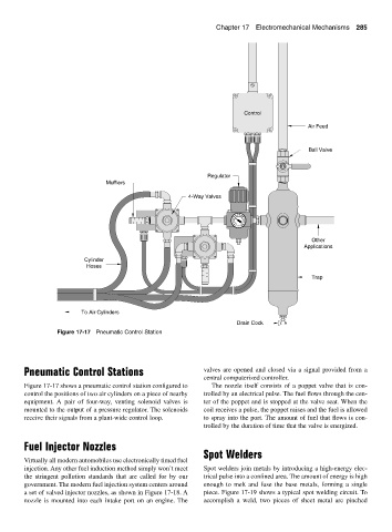
Figure 17-17 Pneumatic Control Station
Pneumatic Control Stations valves are opened and closed via a signal provided from a
central computerized controller.
Figure 17-17 shows a pneumatic control station configured to The nozzle itself consists of a poppet valve that is con-
control the positions of two air cylinders on a piece of nearby trolled by an electrical pulse. The fuel flows through the cen-
equipment. A pair of four-way, venting solenoid valves is ter of the poppet and is stopped at the valve seat. When the
mounted to the output of a pressure regulator. The solenoids coil receives a pulse, the poppet raises and the fuel is allowed
receive their signals from a plant-wide control loop. to spray into the port. The amount of fuel that flows is con-
trolled by the duration of time that the valve is energized.
Fuel Injector Nozzles
Spot Welders
Virtually all modern automobiles use electronically timed fuel
injection. Any other fuel induction method simply won’t meet Spot welders join metals by introducing a high-energy elec-
the stringent pollution standards that are called for by our trical pulse into a confined area. The amount of energy is high
government. The modern fuel injection system centers around enough to melt and fuse the base metals, forming a single
a set of valved injector nozzles, as shown in Figure 17-18. A piece. Figure 17-19 shows a typical spot welding circuit. To
nozzle is mounted into each intake port on an engine. The accomplish a weld, two pieces of sheet metal are pinched