
Page 156 -
P. 156
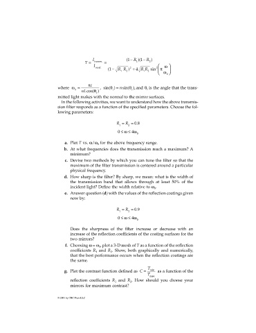
I (1 − R )(1 − R )
T = transm. = 1 2
I ω
incid. − 2 R R sin π
2
(1 RR ) + 4
1 2 1 2 ω 0
where ω = πc , sin( ) θ and θ is the angle that the trans-
θ = nsin( ),
0 i t t
nLcos( θ )
t
mitted light makes with the normal to the mirror surfaces.
In the following activities, we want to understand how the above transmis-
sion filter responds as a function of the specified parameters. Choose the fol-
lowing parameters:
R = R = 08.
1 2
0 ≤ ω ≤ 4ω
0
a. Plot T vs. ω/ω for the above frequency range.
0
b. At what frequencies does the transmission reach a maximum? A
minimum?
c. Devise two methods by which you can tune the filter so that the
maximum of the filter transmission is centered around a particular
physical frequency.
d. How sharp is the filter? By sharp, we mean: what is the width of
the transmission band that allows through at least 50% of the
incident light? Define the width relative to ω .
0
e. Answer question (d) with the values of the reflection coatings given
now by:
R = R = 09.
1 2
0 ≤ ω ≤ 4ω
0
Does the sharpness of the filter increase or decrease with an
increase of the reflection coefficients of the coating surfaces for the
two mirrors?
f. Choosing ω = ω , plot a 3-D mesh of T as a function of the reflection
0
coefficients R and R . Show, both graphically and numerically,
2
1
that the best performance occurs when the reflection coatings are
the same.
T
g. Plot the contrast function defined as C = min as a function of the
T
max
reflection coefficients R and R . How should you choose your
1
2
mirrors for maximum contrast?
© 2001 by CRC Press LLC