Page 252 -
P. 252

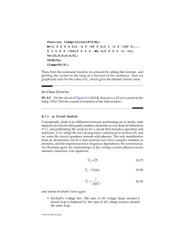
function ilamp=circuit872(RL)
                                M=[1 0 0 0 0 0;1 -1 0 -50 0 0;0 1 -1 0 -100 0;...
                                0 1 0 0 0 -300;0 0 1 0 -RL 0;0 0 0 1 -1 -1];
                                Vs=[5;0;0;0;0;0];
                                VI=M\Vs;
                                ilamp=VI(5);

                             Then, from the command window, we proceed by calling this function and
                             plotting the current in the lamp as a function of the resistance. Then we
                             graphically read for the value of R , which gives the desired current value.
                                                           L


                             In-Class Exercise

                             Pb. 8.5 For the circuit of Figure 8.1, find R  that gives a 22-mA current in the
                                                                  L
                             lamp. (Hint: Plot the current as function of the load resistor.)


                             8.7.3  ac Circuit Analysis
                             Conceptually, there is no difference between performing an ac steady-state
                             analysis of a circuit with purely resistive elements, as was done in Subsection
                             8.7.1, and performing the analysis for a circuit that includes capacitors and
                             inductors, if we adopt the tool of impedance introduced in Section 6.8, and
                             we write the circuit equations instead with phasors. The only modification
                             from an all-resistors circuit is that matrices now have complex numbers as
                             elements, and the impedances have frequency dependence. For convenience,
                             we illustrate again the relationships of the voltage-current phasors across
                             resistors, inductors, and capacitors:

                                                           ˜
                                                                ˜
                                                           V =  IR                         (8.17)
                                                            R
                                                          ˜
                                                         V =  ˜ ( I j Lω  )                (8.18)
                                                           L

                                                          ˜
                                                         V =    I ˜                        (8.19)
                                                           C   ω
                                                              (jC )
                             and restate Kirchoff’s laws again:

                                • Kirchoff’s voltage law: The sum of all voltage drops around a
                                   closed loop is balanced by the sum of all voltage sources around
                                   the same loop.


                             © 2001 by CRC Press LLC
   247   248   249   250   251   252   253   254   255   256   257