Page 192 - Embedded Microprocessor Systems Real World Design
P. 192

I call these data outputs action codes. They are useful for debug and as a means
                of  correlating software execution with the real world as captured on a logic ana-
                lyzer or digital storage oscilloscope (DSO) .
                   There are many ways to capture the action codes. They center around two basic
                techniques: generating the data for hardware that may or may not be connected
                and storing the information in memory for later retrieval. Both techniques have
                 advantages and drawbacks.


                  ~~
                 Hardware Output

                The hardware output technique depends on getting debug data (action codes) to
                 the outside world in some simple 8-bit, 16-bit, or even 32-bit format. Ideally, the
                firmware will not check to see whether the debug hardware is connected. This is
                 because reliable debug depends on the firmware operating the same, regardless of
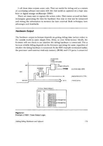
                whether the debug hardware is connected. In the 8031 example mentioned earlier,
                 the processor used external read-only memory (ROM) and I/O ports. I connected


                                                   I/O DECODE
                                                   LOGIC
                                                   2:4 MULTIPLEXER
                                                   --  TO
                          -WR                      0
                                                               -
                                                        - OTHER CIRCUITS
                                      ADDRESS                   STROBE   (CLOCKS ANALYZER)
                                       LATCH
                     8051
                                                                A0      (INDICATES DATA NPE)

                       ADGAD7                                           (TRACE DATA)


                                       NPICAL TRACE RESULT:
                                       DATA   A0
                                       01   0    DEBUGDATA
                                       02   0    DEBUGDATA
                                       05   0    DEBUGDATA
                                       80   0    DEBUGDATA
                                       FF   1    MOTOR SPEED PARAMETER
                                       7C   0    DEBUGDATA
                                       21   1    MOTOR SPEED PARAMETER
                                       59   0    DEBUGDATA
                                       47   0    DEBUGDATA


                 Figure 6.1
                 Example of 8051 Trace Output Logic.


                 Adding Debug Hardware and  Softuare                                  173
   187   188   189   190   191   192   193   194   195   196   197