
Page 193 - Embedded Microprocessor Systems Real World Design
P. 193
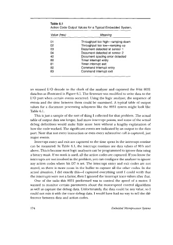
Table 6.1
                               Action Code Output Values for a Typical  Embedded System.
                               Value (hex)                   Meaning

                               01                Throughput too high-ramping  down
                               02                Throughput too low-ramping  up
                               03                Document detected at sensor  1
                               04                Document detected at sensor 2
                               40                Document spacing error detected
                               80                Timer  interrupt entry
                               81                Timer interrupt exit
                               82                Command interrupt entry
                               83                Command interrupt exit


                   an unused  1/0 decode to the clock of the analyzer and captured the 8-bit 8031
                   data bus as illustrated in Figure 6.1. The firmware was modified to write data to the
                   1/0 port when certain events occurred. Using the logic analyzer, the sequence of
                   events and the time between  them could be examined. A typical table of  output
                   values for a document processing subsystem like the 8031 system might look like
                   Table 6.1.
                      This is just a sample of the sort of thing I collected for that problem. The actual
                   table of output data was longer, had more interrupt points, and some of the actual
                   debug definitions would make little sense here without a lengthy explanation  of
                   how the code worked. The significant events are indicated by an output to the data
                   port. Note that not every instruction or even every subroutine call is captured, just
                   major events.
                      Interrupt entry and exit are captured so the time spent in the interrupt routine
                   can be measured. In Table 6.1, the interrupt routines use data values of  80h and
                   above. This is because most logic analyzers can be programmed to ignore data using
                   a binary mask. If no mask is used, all the action codes are captured. If you know the
                   interrupts are not involved in the problem, you can configure the analyzer to ignore
                   any action codes where bit D7 is set. The interrupt entry and exit codes are not
                   stored, so  there is more room in the buffer to capture all the other codes. In the
                   actual situation, I did exactly this-I   captured everything until I could verify that
                   the interrupts were not a factor, then I ignored the interrupt trace values after that.
                      One of  the  tasks this 8031 performed was  to control the  speed of  a motor. I
                   wanted to monitor certain parameters about the motor-speed control algorithms
                   as well as capture the debug data. Unfortunately, the data could be any value, so I
                   could not mix it with the trace debug data. I would have had no way to tell the dif-
                   ference between data and action codes.


                   174                                             Embedded Microprocessor System