
Page 114 - Academic Press Encyclopedia of Physical Science and Technology 3rd BioTechnology
P. 114
P1: GNB Final Pages
Encyclopedia of Physical Science and Technology EN005F-954 June 15, 2001 20:48
Fiber-Optic Chemical Sensors 827
tor multiple analytes. A CCD detector is used to monitor
and spatially resolve the signal obtained from each mi-
crosphere. Imaging and data analysis software are used to
calculate the analyte concentrations.
Multianalyte fiber-optic chemical sensors are in the first
stages of research and development. Due to their impor-
tance for many analytical applications, it is expected that
research efforts will continue to advance the capabilities
of such sensors.
B. Distributed Chemical Sensing
Distributed optical fiber sensors are capable of spatially
monitoring analyte concentrations along an optical fiber.
Sensing elements are deposited longitudinally along the
optical fiber and the signals obtained from each sensing
FIGURE 20 Multianalyte fiber-optic chemical sensor with differ-
ent indicators immobilized in polymers attached to an imaging element can be localized to a specific position along the
fiber. CO 2 -sensitive matrices (A and B), pH-sensitive matrix (C), fiber using a temporal feature of the signal. Distributed
and O 2 -sensitive matrices (D and E). [Reprinted with permission
optical fiber sensors are needed in environmental appli-
from Ferguson, J. A., Healey, B. G., Bronk, K. S., Barnard, S. M.,
cations such as detecting pollutant concentrations at dif-
and Walt, D. R. (1997). Anal. Chim. Acta 340, 123–131.]
ferent water depths (e.g., rivers and lakes). Distributed
optical fiber sensors can identify a layer of sediment or
A more recent approach for multianalyte sensing with water depth where the pollutant concentration is higher
imaging fibers is based on the ability of each individual and thus provide valuable information about the clean-
fiber to carry its own light signal. Thus, by attaching a ing strategy to be employed. Distributed optical fiber
sensing material to each individual fiber, an array of thou- sensors are also useful for industrial applications where
sands of sensing elements can be constructed on an imag- monitoring analyte gradients inside chemical or biolog-
ing fiber. In practice, the sensing elements are prepared by ical reactors may provide information about the process
immobilizing fluorescent indicators on microsphere sur- efficiency.
faces. The microspheres are distributed on the end of an The distributed signals can be measured and spatially
imaging fiber containing thousands of microwells. These resolved by an optical time-domain reflectometry tech-
microwells are fabricated by selectively etching the in- nique. An optical time domain reflectometer is based on
dividual cores on the tip of the imaging fiber as shown the measurement of backscattered light attained from a
in Fig. 21. Since different indicators are immobilized on light pulse propagating through an optical fiber. Light is
different microspheres, the array can be used to moni- backscattered because of inhomogeneities and impurities
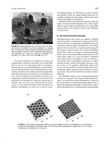
FIGURE 21 Scanning force micrograph (SFM) of a sensing microsphere array on an imaging fiber. (a) The microwells
are fabricated by selectively etching the cores of the individual fibers composing the imaging fiber. (b) The sensing
microspheres are distributed in the microwell.