
Page 23 - Academic Press Encyclopedia of Physical Science and Technology 3rd Chemical Engineering
P. 23
P1: LDK Revised Pages
Encyclopedia of Physical Science and Technology EN001H-01 May 7, 2001 16:18
20 Absorption (Chemical Engineering)
The number of trays is determined by dividing the the-
oretical number of stages, which is obtained from the rela-
tionships in Section III, by the appropriate tray efficiency.
It is best to use experimental efficiency data for the sys-
tem when available, but caution is required when extend-
ing such data to column design, because tray efficiency
depends on tray geometry, liquid and gas loads, and phys-
ical properties, and these may vary from one contactor
to another. In the absence of data, absorption efficiency
FIGURE 19 Flexitray valve unit (courtesy of Koch Engineering
can be estimated using O’Connell’s empirical correlation.
Company, Inc.).
This correlation should not be used outside its intended
range of application.
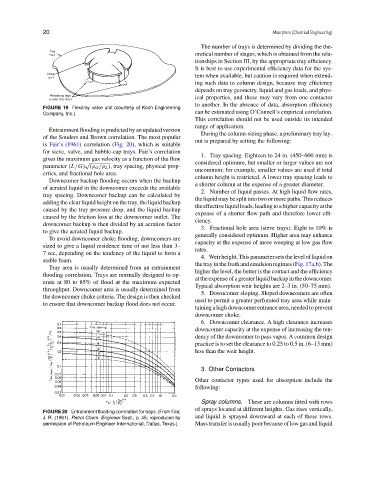
Entrainment flooding is predicted by an updated version
During the column-sizing phase, a preliminary tray lay-
of the Souders and Brown correlation. The most popular
out is prepared by setting the following:
is Fair’s (1961) correlation (Fig. 20), which is suitable
for sieve, valve, and bubble-cap trays. Fair’s correlation
1. Tray spacing. Eighteen to 24 in. (450–600 mm) is
gives the maximum gas velocity as a function of the flow
√ considered optimum, but smaller or larger values are not
parameter (L/G) (ρ G /ρ L ), tray spacing, physical prop-
uncommon; for example, smaller values are used if total
erties, and fractional hole area.
column height is restricted. A lower tray spacing leads to
Downcomer backup flooding occurs when the backup
a shorter column at the expense of a greater diameter.
of aerated liquid in the downcomer exceeds the available
2. Number of liquid passes. At high liquid flow rates,
tray spacing. Downcomer backup can be calculated by
the liquid may be split into two or more paths. This reduces
adding the clear liquid height on the tray, the liquid backup
theeffectiveliquidloads,leadingtoahighercapacityatthe
caused by the tray pressure drop, and the liquid backup
expense of a shorter flow path and therefore lower effi-
caused by the friction loss at the downcomer outlet. The
ciency.
downcomer backup is then divided by an aeration factor
3. Fractional hole area (sieve trays). Eight to 10% is
to give the aerated liquid backup.
generally considered optimum. Higher area may enhance
To avoid downcomer choke flooding, downcomers are
capacity at the expense of more weeping at low gas flow
sized to give a liquid residence time of not less than 3–
rates.
7 sec, depending on the tendency of the liquid to form a
4. Weirheight.Thisparametersetsthelevelofliquidon
stable foam.
the tray in the froth and emulsion regimes (Fig. 17a,b). The
Tray area is usually determined from an entrainment
higher the level, the better is the contact and the efficiency
flooding correlation. Trays are normally designed to op-
attheexpenseofagreaterliquidbackupinthedowncomer.
erate at 80 to 85% of flood at the maximum expected
Typical absorption weir heights are 2–3 in. (50–75 mm).
throughput. Downcomer area is usually determined from
5. Downcomer sloping. Sloped downcomers are often
the downcomer choke criteria. The design is then checked
used to permit a greater perforated tray area while main-
to ensure that downcomer backup flood does not occur.
taining a high downcomer entrance area, needed to prevent
downcomer choke.
6. Downcomer clearance. A high clearance increases
downcomer capacity at the expense of increasing the ten-
dency of the downcomer to pass vapor. A common design
practice is to set the clearance to 0.25 to 0.5 in. (6–13 mm)
less than the weir height.
3. Other Contactors
Other contactor types used for absorption include the
following:
Spray columns. These are columns fitted with rows
of sprays located at different heights. Gas rises vertically,
FIGURE 20 Entrainment flooding correlation for trays. (From Fair,
J. R. (1961). Petrol Chem. Engineer Sept., p. 45; reproduced by and liquid is sprayed downward at each of these rows.
permission of Petroleum Engineer International, Dallas, Texas.) Mass transfer is usually poor because of low gas and liquid