
Page 21 - Academic Press Encyclopedia of Physical Science and Technology 3rd Chemical Engineering
P. 21
P1: LDK Revised Pages
Encyclopedia of Physical Science and Technology EN001H-01 May 7, 2001 16:18
18 Absorption (Chemical Engineering)
TABLE II Characteristics of Random Packings a
2
3
Surface area (m /m ) Packing factor (m −1 )
Nominal size (mm) 25 38 50 75 90 25 38 50 75 90
Type
Raschig ring (metal) 185 130 95 66 — 450 270 187 105 —
Pall ring (metal) 205 130 115 — 92 157 92 66 — 53
®
Intalox Metal Tower Packing — — — — — 135 82 52 43 —
Raschig ring (ceramic) 190 120 92 62 — 510 310 215 120 —
Berl saddle (ceramic) 250 150 105 — — 360 215 150 — —
®
Intalox saddle (ceramic) 255 195 118 92 — 320 170 130 70 —
®
Intalox saddle (plastic) 206 — 108 88 — 105 — 69 50 —
Pall ring (plastic) 205 130 100 — 85 170 105 82 — 52
a
(From Perry, R. H. (ed.) (1985). “Chemical Engineer’s Handbook,” 6th ed., McGraw-Hill, New York.)
this pressure drop at the design and liquid loads. Pressure For structured packings the correlation of Rocha et al.
drops of 1.5–1.7 in. H2O per foot are representative of (1996) has been well validated for a number of packings
incipient flooding and values this high are to be avoided. tested in larger equipment. Even if experimental data are
Packed height is determined from the relationships in available, one must be cautious in applying data taken in
Section III. Application of these relationships requires small laboratory columns to designs of large commercial
knowledge of the liquid and gas mass transfer coefficients. contactors.
It is best to obtain these from experimental data on the sys-
tem if available, but caution is required when extending
2. Tray Columns
such data to column design, because mass transfer coeffi-
cients depend on packing geometry, liquid and gas distri- A typical arrangement (Fig. 17) consists of a vertical tower
bution, physical properties, and gas and liquid loads, and fitted with horizontal plates or trays, on which liquid and
these may vary from one contactor to another. gas are contacted. Each tray is equipped with gas passages,
In the absence of experimental data, mass transfer co- which may be perforations in the tray floor or other de-
efficients (and hence heights of transfer units) can be es- vices such as valves or bubble caps that disperse the rising
timated by generalized models. A popular and easy to gas into the liquid layer. The liquid layer on the tray is
use correlation for random packings is that of Bolles and maintained by the outlet weir. Liquid descends from each
Fair (1982). The earlier correlations of Onda et al. (1968) tray to the tray below via a downcomer.
and Bolles and Fair are also useful for random packings. Liquid enters the column and flows across the top tray,
whereitcontactstherisinggastoformafroth,emulsion,or
spray-type dispersion (Fig. 18). It then overflows the weir
into the downcomer, which separates gas from the liquid,
and carries liquid by gravity to the tray below. The liquid
then flows across the next tray, and the process is repeated.
Liquid is thus contacted with gas in a stagewise manner.
Two types of trays are most common: sieve trays and
valve trays. A sieve tray is a simple perforated plate. Gas
issues from the perforations to give a multiorifice effect;
liquid is prevented from descending the perforations or
“weeping” by the upward motion of the gas. At low gas
flow rates, the upward gas motion may be insufficient to
prevent weeping.
In valve trays, the perforations are equipped with valve
units (Fig. 19). At high gas rates, the gas force opens the
valves, thus providing area for gas flow. At low gas rates,
21
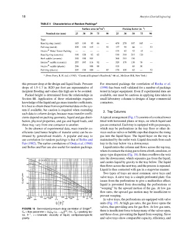
FIGURE 16 Generalized pressure drop correlation of Strigle .
C s = flow parameter = U s [ρ g /(ρ L − ρ g )] 0.5 , ft/s. F p = packing fac- there is insufficient force to keep many of the valves open,
tor, ft −1 , ν = kinematic viscosity of liquid, centipoises/specific and these close, preventing the liquid from weeping. Sieve
gravity. and valve trays show comparable capacity, efficiency, and