
Page 18 - Academic Press Encyclopedia of Physical Science and Technology 3rd Chemical Engineering
P. 18
P1: LDK Revised Pages
Encyclopedia of Physical Science and Technology EN001H-01 May 7, 2001 16:18
Absorption (Chemical Engineering) 15
The interface equilibrium is written at the interface. maximum when the solvent is volatile (e.g., ammonia–
water absorption).
I
I
I
y j,n = m x (33) When solute is absorbed rapidly, the rate of heat libera-
j,n j,n
L
V
In Eq. (31c), N j,n and N j,n are the mass transfer rates. tion is largest near the bottom of the absorber, causing the
These are calculated from multicomponent mass transfer equilibrium curve to bend upward at the solute-rich end,
equations. The equations used take into account the mass while remaining relatively unaffected by the heat of solu-
transfer coefficients and interfacial areas generated in the tion at the lean end of the absorber. This may sometimes
specific contactor, reaction rates, heat effects, and any in- lead to a pinched condition at the rich end of the absorber.
teractions among the above processes. When this type of pinching is a concern, it is customary
The above equations, including those describing the either to provide cooling coils inside the absorber or to
mass transfer rates on each stage, are solved simultane- divert a liquid stream through an external cooler and then
ously for all stages. Solution of these nonlinear equations return it to the next lower tray in the column.
is complex and usually requires a computer. Newton’s nu- Other than the heat of solution, heat effects that may
merical convergence technique, or a variant of it, is con- influence absorber performance are solvent vaporization,
sidered to be most effective in solving these equations. sensible heat exchange between the gas and the liquid, and
loss of sensible heat due to cooling coils or atmospheric
cooling. Detailed discussion on heat effects in absorption
D. Heat Effects in Absorption
is presented in the text by Sherwood et al. (1975).
When absorption liberates a considerable quantity of heat,
and if a large quantity of solute is absorbed, the solution
temperature rises. This reduces the solubility of the solute IV. ABSORBER DESIGN
in the liquid, thus counteracting absorption.
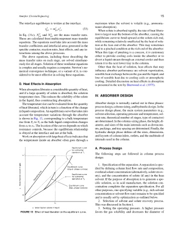
The temperature rise can be evaluated from the quantity Absorber design is normally carried out in three phases:
of heat liberated, which in turn is a function of the change processdesign,columnsizing,andhydraulicdesign.Inthe
in liquid composition. An equilibrium curve that takes into process design phase, the main system parameters (e.g.,
account the temperature variations through the absorber solvent selection, operating pressure and temperature, sol-
is shown in Fig. 13, corresponding to a bulk temperature vent rate, theoretical number of stages, type of contactor)
rise from T 2 to T 1 as the bulk liquid composition changes are determined. In the column-sizing phase, the height, di-
from x 2 to x 1 . The location of the curves depends on which ameter, and sizes of the main internals such as downcom-
resistance controls, because the equilibrium relationship ers, packings, and tray spacing are determined. Finally, the
is obeyed at the interface and not at the bulk. hydraulic design phase defines all the sizes, dimensions,
Work on absorption with large heat effects indicates that and layouts of column inlets, outlets, and the multitude of
the temperature inside an absorber often goes through a internals used in the column.
A. Process Design
The following steps are followed in column process
design:
1. Specification of the separation. A separation is spec-
ified by defining column feed flow rate and composition,
overhead solute concentration (alternatively, solute recov-
ery), and the concentration of solute (if any) in the lean
solvent. If the purpose of absorption is to generate a spe-
cific solution, as in acid manufacture, the solution con-
centration completes the separation specification. For all
other purposes, one specifying variable (e.g., rich solvent
concentration or solvent flow rate) remains to be specified
and is usually set by optimization as outlined below.
2. Selection of solvent and solute recovery process.
This was discussed in Section I.
3. Setting the operating pressure. A higher pressure
FIGURE 13 Effect of heat liberation on the equilibrium curve. favors the gas solubility and decreases the diameter of