
Page 248 - Academic Press Encyclopedia of Physical Science and Technology 3rd Chemical Engineering
P. 248
P1: FYK/GJK P2: FJU Final Pages
Encyclopedia of Physical Science and Technology EN005B-205 June 15, 2001 20:24
Electrochemical Engineering 155
To date, most simulations have been based on the finite pirical data. If operation significantly below the limiting
difference technique or the finite element method. In both current is anticipated, concentration overpotentials can be
methods the domain of interest is divided into smaller neglected; at higher current densities concentration over-
subdomains. Trial solutions for one of the variables are potential estimates are obtainable from Eq. (27).
assumed, and these are corrected through continued it- Current efficiency is defined as the fraction of the total
eration. Convergence is assumed when the solutions do current participating in the desired reaction. The portion
not change significantly between iterations. While con- of the current that produces undesired products is usu-
vergence for secondary and tertiary current distribution ally a function of the current density; generally, parasitic
problems is not ensured, general techniques for promot- reactions are more likely to be favored at higher current
ing convergence are available. densities. Overall energy efficiency is the product of the
In most cases the accuracy of the solution increases voltage efficiency times the current efficiency. In an op-
as the domain of interest is more finely divided; how- timization it is useful to examine the magnitudes of the
ever, the computer calculation time also increases with the losses from the various sources and to determine whether
finer division. An advantage of using finite element and fi- the major losses can be minimized.
nite difference techniques is that commercial routines are Consider the production of chlorine and caustic soda
available to solve some of the pertinent euqations. from brine. This process is one of the most important com-
Other methods such as orthogonal collocation and mercial, electrolytic syntheses; worldwide production of
boundary element techniques have also been used. The chlorine is currently 30 million tons per year. In one elec-
relative advantages of using the various methods usually trochemical route the overall reaction is
involve trade-offs among factors such as programming
2 NaCl + 2H 2 O = 2 NaOH + Cl 2 + H 2 , (31)
ease, accuracy of solution, storage capability of the com-
puter, and availability of software. and the electrode reactions are
2Cl = Cl 2 + 2 e at the anode (32)
−
B. Technical Factors
−
2H 2 O + 2e = 2OH + H 2 at the cathode. (33)
Effective system design depends on the proper application 2
A modern cell operates at approximately 300 mA/cm
of the principles of thermodynamics, kinetics, and trans-
◦
and 85 C; the anode electrolyte (anolyte) is 15% NaCl,
port phenomena. Reliable design data are invariably ob-
and the cathode electrolyte (catholyte) is 30% NaOH. A
tained empirically because ab initio computation of design
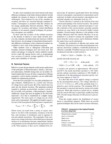
breakdown of the thermodynamic potential and the volt-
parameters, such as kinetic quantities, are not sufficiently
age losses appears in Table III.
reliable for engineering purposes.
It is clear that most of the applied voltage is required
From the basic principles we can make preliminary de-
for the decomposition process. The voltage efficiency is
sign estimates. Inefficiencies in a system arise because
2.2 V/3.7 V = 0.6, (i.e., 60% of the potential drop is re-
of voltage losses and because all of the current does not
quired to carry out the reaction). The remaining 40% of
enter into the desired reactions. The minimum potential
the potential is converted into heat by various irreversible
required to perform an electrolytic reaction is given by
processes. When this reaction is carried out in a modern
the reversible cell potential, a thermodynamic quantity.
cell, the current efficiency is quite high, usually more than
Additional voltage that must be applied at the electrodes
95%. Overall energy efficiency for this process is just un-
represents a loss that is manifested in a higher energy
der 60%.
requirement. The main causes of voltage loss are ohmic
From this simple analysis the distribution of energy
drops and overpotentials. The applied potential is equal to
losses is immediately apparent. While there are several
thesumofthelossesplusthethermodynamicrequirement:
general techniques that can be used to increase efficiency,
V applied = E + V ohm + η si + η ci (30)
i i
TABLE III Components of the Applied Potential
Ohmic losses can result from a variety of causes: resis- in a Chlor–Alkali Cell
tance to ion flow in the electrolyte, resistance in the bus
Thermodynamic potential 2.2 V
bars, and resistance in membranes used to separate an-
Anodic overpotential 0.1
ode and cathode electrolytes. The magnitude of the resis-
Ohmic losses 0.6
tances may change with time as films build up on electrode
Membrane loss 0.5
surfaces or as membranes become contaminated. Surface
Cathodic overpotential 0.3
overpotentials can be estimated from rate expressions such
Terminal voltage 3.7 V
as the Tafel equation, or they can be evaluated from em-