
Page 346 - Academic Press Encyclopedia of Physical Science and Technology 3rd Chemical Engineering
P. 346
P1: GLQ Final Pages
Encyclopedia of Physical Science and Technology EN009K-419 July 19, 2001 20:57
Membranes, Synthetic, Applications 281
TABLE I Primary Synthetic Membrane Applications and
Driving Forces
Function or application Typical driving force type
Membrane dialysis (D) Concentration
Microfiltration (MF) Pressure (10–25 psi)
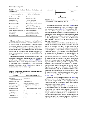
Ultrafiltration (UF) Pressure (10–100 psi) FIGURE 1 Idealized membrane process showing feed (N F ), non-
permeate (N NP ) and permeate (N P ) streams.
Nanofiltration (NF) Pressure (100–500 psi)
Reverse osmosis (RO) Pressure (minus osmotic pressure)
(100–1500 psi)
Most membrane operations indicated in Table I are run
Gas separation (GS) Partial pressure (10–1000 psi)
as continuous steady state processes with a feed, permeate,
Pervaporation (PV) Activity, effective partial pressure
and retentate stream (see Fig. 1). For example, in dialy-
Carrier facilitated transport (CFT) Activity, concentration
sis, a feed stream comprising blood with urea and other
Ion conduction Ion concentration, voltage
metabolic by-products passes across the upstream face of
Ion exchange Electrochemical interactions
a membrane while an electrolyte solution without these
Affinity separation Biospecific interactions
by-products passes across the lower face of the membrane.
A flux of by-products (A) occurs into the downstream
where it is taken away as a permeate and the purified blood
Many controlled release devices are not “membranes” leaves as nonpermeate.
by the conventional definition, since only transient release In microfiltration and ultrafiltration a feed stream con-
of an active agent, without permeation occurring between taining suspended particles passes across the upstream
an upstream and a downstream, is typical. Nevertheless, face of a membrane at a higher pressure than exists at
some controlled release units do operate with a concen- the downstream. This pressure driving force motivates the
tration driving force to achieve effectively steady state suspendingfluid(usuallywater)topassthroughphysically
release from the internal reservoir of the device to the ex- observable pores in the membrane. This process achieves
ternal surrounding. Such processes are included here for a concentration of the particles or macromolecules in
completeness. the nonpermeate stream and produces essentially pure
Membrane reactors and contactors for extraction, gas particle-free permeate. Such processes are extremely use-
absorption, or membrane distillation represent extensions ful for processing of thermally labile feeds and are even
of various types of the membranes in Table I and Table II. being used as replacements for sand filters in water clarify-
Nevertheless, these cases, along with controlled release ing and purification. Cost is generally an important issue,
of application, will be considered briefly to illustrate how so minimization of the membrane resistance A in Eq. (1)
the basic membrane types in Table I can be applied in requires a small effective membrane thickness to achieve
unconventional, ever-expanding ways. high fluxes at low pressure differences. This theme, the
need to achieve a very small effective thickness, runs
throughout most of the membrane applications, since cost
TABLE II Characteristic Penetrant Size (Diameter) Spectrum is related to required membrane area and required mem-
for Nonpermeating Species
brane area is inversely proportional to the achievable flux
Application Nonpermeating species size (Koros, 1995).
In the other pressure-driven separations in Table I, the
Conventional >200,000 ˚ A
(nonmembrane) filtration difference in size between the permeating component A
and rejected components B, C, etc., is progressively re-
Microfiltration (MF) 1,000–200,000 ˚ A
duced in NF vs RO vs GS. This shift in size discrimination
Ultrafiltration (UF) 20–100 ˚ A (MW 10,000–100,000)
requirements is illustrated in Table II.
Membrane dialysis (D) 5–50 ˚ A (MW 50–10,000 daltons)
Recently, impressive strides have been made in con-
Nanofiltration (NF) 5–20 ˚ A
trolling the effective sizes of suspended macromolecules
Reverse osmosis (RO) 3–5 ˚ A (hydrated microsolutes and ions)
by adjusting ionic strength and pH to selectively alter the
Gas separation (GS) 3–5 ˚ A
effective size in solution of nominally similar molecular
Pervaporation (PV) 3–5 ˚ A
weight components. This approach allows the smaller of
Carrier facilitated 3–10 ˚ A (gases and dissolved solutes) the two components to pass through the membrane with
transport (CFT)
the suspending solvent to the permeate to allow fraction-
Ion conduction (IC) 3–5 ˚ A
ation of two similarly sized dissolved macromolecules.