
Page 347 - Academic Press Encyclopedia of Physical Science and Technology 3rd Chemical Engineering
P. 347
P1: GLQ Final Pages
Encyclopedia of Physical Science and Technology EN009K-419 July 19, 2001 20:57
282 Membranes, Synthetic, Applications
3
2
Ultimately, strictly hydrodynamic sieving of a suspend- (g/sec cm ), and the solvent specific volume, ˆv A (cm /g).
˚
ing solvent A (typically <3–4 A) away from suspended B This volumetric flux, relates to the average velocity in a
becomes inadequate and molecular forces enter as domi- pore, U Ap as follows (Carman, 1937):
¯
nant factors. Arguments are still heard regarding the need
¯
n A ˆv A = ε[L/L e ]U Ap , (2)
for combined hydrodynamic and molecular factors in NF
separations. Nevertheless, the boundary at which molecu- where ε is the membrane porosity (pore volume/total vol-
lar factors become dominant is typically set between ultra- ume) and L/L e is the ratio of the physical thickness of the
filtration and nanofiltration for such pressure-driven cases. membrane to the “effective” distance a flowing penetrant
Indeed, by their nature, membranes combine thermo- must travel due to complex morphology of the medium.
dynamically based partitioning and kinetically based mo- For straight cylindrical pores oriented perpendicular to the
bility discrimination in an integrated separation unit. In membrane upstream and downstream surfaces, L/L e = 1,
membranes with large pores relative to the size of indi- and the expression for flux relates simply to the fluid vis-
vidual molecules, the thermodynamic partitioning aspects cosity, η, pore diameter, d p , and pressure drop across the
are practically negligible in most cases. Except for MF and membrane,
p, according to Eq. (3) (Cheryan, 1986):
UF, however, both aspects must be considered to some de- 2
(n A ˆv A ) o = ε d p 32ηL
p. (3)
gree depending upon the specific application. Examples
of the limiting cases between these two situations can be The subscript “o” indicates that this flux is for solvent
seen in the case of separation of O 2 and N 2 using either “A” without the presence of rejected solute “B.” This
carrier-facilitated transport or molecular sieving mecha- model is appropriate for membranes that have straight
nisms for gas separation. In the case of carrier-facilitated pores; however, such membranes are not typical of most
transport, thermodynamics dominates the selective sepa- industrial membranes. Not only are the rate limiting pores
ration of one gas from another. In the case of molecular in the actual working skin layer tortuous, but a complex
sieving, size and shape dominate, but in a more complex porous support layer is generally present that supports the
manner related to actual molecular architecture as com- working skin layer. In well-made sieving membranes, the
pared to simple hydrodynamic sieving seen in microfiltra- porous support is ideally “invisible” to the transport pro-
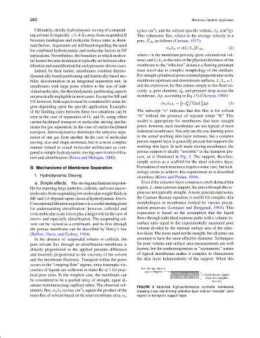
tion and ultrafiltration (Koros and Mahajan, 2000). cess, as is illustrated in Fig. 2. The support, therefore,
simply serves as a scaffold for the ideal selective layer.
B. Mechanisms of Membrane Separation Formation of such structures requires some care, but tech-
nology exists to achieve this requirement as is described
1. Hydrodynamic Sieving
elsewhere (Koros and Pinnau, 1994).
a. Simple effects. The sieving mechanism responsi- Even if the selective layer comprises a well-defined thin
ble for rejecting large particles, colloids, and even macro- region, L, atop a porous support, the pores through this re-
molecules from suspending low molecular weight fluids in gion are not typically straight. A more general expression,
MF and UF depends upon classical hydrodynamic forces. the Carman–Kozeny equation, is useful for complex skin
Conventional filtration experience is a useful starting point morphologies in membranes formed by various precip-
for understanding ultrafiltration; however, colloidal and itation processes (Leenaars and Burggraaf, 1985). This
even molecular scale forces play a larger role in the case of expression is based on the assumption that the liquid
micro- and especially ultrafiltration. The suspending sol- flows through individual tortuous paths with a volume-to-
vent can be viewed as a continuum, and its flow through surface ratio equal to the experimentally measured pore
the porous membrane can be described by Darcy’slaw volume divided by the internal surface area of the selec-
(Belfort, Davis, and Zydney, 1994). tive layer. The pores need not be straight, but all pores are
In the absence of suspended solutes or colloids, the assumed to have the same effective diameter. Techniques
pure solvent flux through an ultrafiltration membrane is for pore volume and surface area measurements are well
directly proportional to the applied pressure difference known, but the nonhomogeneous or “asymmetric” nature
and inversely proportional to the viscosity of the solvent of typical membranes makes it complex to characterize
and the membrane thickness. Transport within the pores the skin layer independently of the support. When this
occurs in the “creeping flow” regime, since kinematic vis-
cosities of liquids are sufficient to make Re 1 for prac-
tical pore sizes. In the simplest case, the membrane can
be considered to be a packed array of straight, equal di-
ameter nonintersecting capillary tubes. The observed vol- FIGURE 2 Idealized high-performance synthetic membrane
2
umetric flux, n A ˆv A (cc/sec cm ), equals the product of the showing a top rate-limiting selective layer and an “invisible” (with
mass flux of solvent based on the total membrane area, n A regard to transport) support layer.