
Page 191 - Academic Press Encyclopedia of Physical Science and Technology 3rd Analytical Chemistry
P. 191
P1: GRB/MBQ P2: GLM Final Pages
Encyclopedia of Physical Science and Technology EN007C-340 July 10, 2001 14:45
802 Infrared Spectroscopy
the monochromator toward the detector. When the grating ically at 45 . Ideally the beam splitter transmits half the
◦
is rotated to a slightly different angle, the path length dif- radiation striking it and reflects the other half. One type of
ference for beams from adjacent grooves will be slightly beam splitter is a thin layer of germanium coated on an IR-
different, so radiation with a slightly different wavelength transmitting support. The transmitted and reflected beams
will pass through the monochromator. leave the beam splitter at right angles, and both strike mir-
When the spectrometer is set at a given wavelength, the rors, which return the two beams to the beam splitter. The
sample beam and reference beam alternately pass through two beams recombine at the beam splitter and show in-
the monochromator and activate the detector. If the two terference. The radiation leaving the beam splitter may
beams do not have the same intensity because of sam- go back to the source or may go at right angles, passing
ple absorption, an alternating signal is generated and is through the sample and going on to the detector.
used to measure the percent transmission of the sample One of the two mirrors is movable, so its distance from
at that wavelength. The grating angle is changed, and the the beam splitter can be varied. The path length differ-
whole spectrum is generated wavelength by wavelength. ence for the two beams in the interferometer is called the
Usually, several gratings are used for the whole spectral retardation and is two times the displacement of the mov-
range, and a grating may be used in more than one order. able mirror from the equidistant point. If a monochromatic
As the wavelength increases, the slit is widened to allow source such as a laser is used, the radiant energy reaching
more energy through to compensate for decreased source the detector will vary as a cosine function of the retarda-
emission at long wavelengths. tion. The detector response will reach a maximum every
time the retardation is an integral number of wavelengths
of the radiation. At this time the beams from the two mir-
C. Fourier Transform Infrared Spectrometers rors combine at the beam splitter in phase for the beam
In a Fourier transform infrared (FT-IR) spectrometer, there going to the detector and show constructive interference.
If the movable mirror is then moved one-quarter of a wave-
is no monochromator to disperse or separate the radiation
length of radiation, the retardation is changed by one-half
by wavelength. Instead, a whole single-beam spectrum is
generated all at once. The intensities of all of the wave- of a wavelength. The beams from the two mirrors com-
length elements are analyzed simultaneously. Since all the bine at the beam splitter one-half of a wavelenth out of
radiation frequencies reach the detector at the same time, phase for the beam going to the detector and show de-
there is a large signal-to-noise ratio. This is called the structive interference. The detector response as a function
multiplex or Fellgett advantage and is one of the principal of the retardation is called the interferogram. The spec-
advantages that an FT-IR spectrometer has over a disper- trum can be generated from the interferogram by a Fourier
sive instrument. This advantage is particularly noticeable transform. The Fourier transform of a single cosine wave-
for low-energy conditions or where scale expansion is re- type interferogram is a single wavelength, in this case that
quired to bring out very weak bands. There is also an of the laser source.
advantage in that the spectrum can be recorded in less If a polychromatic source is used, its spectrum can be
time. thought of as a series of closely spaced laserlike emission
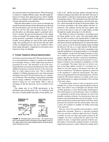
The unique part of an FT-IR spectrometer is the lines, each with its own wavelength and intensity. Each
Michelson-type interferometer (Fig. 10). Radiation from of these generates a cosine function-type interferogram.
the source is made parallel and strikes a beam splitter, typ- The interferogram of a polychromatic source of radiation
is a summation of all the cosine functions for each of the
laserlike resolution elements. An interferometer does not
produceaspectrumbutproducesaninterferogram.Acom-
putermustbeusedtoperformtheFouriertransform,which
generates the spectrum from the interferogram. Once this
is done, the computer is available for further processing
of the spectrum.
Just one scan of the movable mirror produces a whole
single-beam spectrum. However, a spectrum produced
from one scan has a relatively high noise level. Usually,
a number of scans are taken and signal-averaged by the
computer. The noise is reduced by the square root of the
FIGURE 10 Michelson-type interferometer. Left: Source radia-
tion is transmitted and also reflected by a beam splitter to two mir- number of scans. A single-beam spectrum with the sam-
rors. Right: Both mirrors reflect radiation back to the beam splitter, ple in place is stored in the computer memory. A reference
where interference occurs. single-beam spectrum is taken without the sample and is