
Page 194 - Academic Press Encyclopedia of Physical Science and Technology 3rd Analytical Chemistry
P. 194
P1: GRB/MBQ P2: GLM Final Pages
Encyclopedia of Physical Science and Technology EN007C-340 July 10, 2001 14:45
Infrared Spectroscopy 805
and bands from absorbed H 2 O appear in the spectrum in
variable amounts that depend on the technique. One never
knows whether the water is in the sample or the KBr prepa-
ration. Also, spectra of KBr disks are sometimes less re-
producible because of changes in sample polymorphism,
which result from the preparation.
I. Internal Reflectance
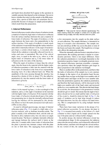
FIGURE 11 Plate used for internal reflection spectroscopy. The
Internalreflectanceresultswhenabeamofradiationinside lower drawing shows the sample in contact with the plate and
a material of relatively high index of refraction is reflected radiation being multiply internally reflected within the plate.
from the surface interface between this and a material of
lower index of refraction. The angle of incidence α is the a few micrometers into the sample on the plate surface
angle between the beam and a line perpendicular to the at each reflection. The sample thickness is immaterial as
surface interface. If the angle of incidence is small, much long as it exceeds a few micrometers. The sample con-
of the radiation is transmitted through the surface interface tact area should go all the way across the plate so none of
and a little is internally reflected. As the angle of incidence the beam can bypass the sample. The lengthwise coverage
gets larger, a certain critical angle α c , is exceeded, after only affects the attenuation intensity.
which all the radiation is internally reflected from the in- When the internally reflected beam is introduced into a
terface and none is transmitted. The sine of the critical spectrometer, the resulting spectrum is similar to a trans-
angle, sin α c is equal to the ratio n 2 /n 1 , where n 1 is the mission spectrum. There is one major difference. Since
higher index of refraction and n 2 is the lower index of the radiation penetration is wavelength dependent in the
refraction on the two sides of the interface. penetration equation, longer wavelengths penetrate more.
When the angle of incidence is larger than the critical The internal reflectance spectrum resembles a transmis-
angle, then the beam in the material with the higher index sion spectrum where the sample thickness gets larger in
of refraction penetrates a little into the material with the direct proportion to the radiation wavelength.
lower index of refraction in the form of an exponentially Thereisanothereffectonthepenetration,andthatisthat
decaying wave. It is then reflected back out. When the the index of refraction of the sample (n 2 ) is not constant.
amplitude of the wave passing through the interface has It changes in the region of an absorption band, becom-
decayed by a factor of (1/e) or about 37%, the reflective ing smaller than average on the high-wave number side of
penetration (d), into the material with the lower index of the band center and larger on the low-wave number side.
refraction is given by From the penetration equation, the radiation penetration,
λ and therefore the band intensity, will be decreased on the
d(1/e) = , (13) high-wave number side of the band center and increased
2 2 1/2
2πn 1 sin α 1 − (n 2 /n 1 )
on the low-wave number side. This distorts the band shape.
where e is the natural log base, λ is the wavelength of the To avoid this, the denominator in the penetration formula
radiation, and α 1 is the angle of incidence in the material should not get too small. This means that the angle of inci-
with the higher index of refraction. If the material with the dence should not be too small and the index of refraction
lower index of refraction should absorb part of the radia- of the crystal n 1 should be relatively high. In Fig. 11, the
tion penetrating into it, then the internally reflected beam angle of incidence can be kept large enough to reduce
leaving the interface will be attenuated by this absorp- the band distortion, but this also reduces the band inten-
tion. Hence we have the name attenuated total reflectance sity. This is compensated for by using multiple internal
(ATR) for this effect. reflections.
As used in infrared spectroscopy, one type of internal There have been many variations in the design of in-
reflectance plate (Fig. 11) is made of a high index of re- ternal reflection accessories. In one design, the plate in
fraction material, such as thallium bromide–iodide. The Fig. 11 is mounted horizontally at the bottom of a shell
plate is usually a few millimeters thick, and the ends are container so that a liquid can be simply spread over the
beveled to allow radiation entry into one end at an angle top of the plate and run without further changes.
inside the plate. The beam is multiply internally reflected In another design, the internal reflectance crystal has
and zigzags between the surfaces until it leaves at the a hemispherical shape. In this arrangement, the radiation
other end. A sample with a lower index of refraction than entersintothecurvedsurface,andisinternallyreflectedoff
the plate is pressed into intimate contact with the plate the flat surface, and then exits through the curved surface.
on one or both sides. The zigzagging beam penetrates In one version of this, the sample is in optical contact