
Page 266 - Academic Press Encyclopedia of Physical Science and Technology 3rd Analytical Chemistry
P. 266
P1: GTM/GRL P2: GNH Final Pages
Encyclopedia of Physical Science and Technology EN009N-406 July 18, 2001 23:32
154 Mass Spectrometry
of the quadrupole mass filter (15–20 cm in length) re-
sulted in a smaller and less expensive instrument pack-
age. Continued refinement culminated in the benchtop
GC/MS instrument, a major step forward in making mass
spectrometric capabilities more widely available. The lim-
ited mass range of the quadrupole mass filter (initially
1000 Da) was not an impediment in GC/MS work, and ad-
equatesensitivitycouldbeobtainedwiththeusualelectron
and chemical ionization sources. Ultimately, quadrupole
mass filters were marketed with upper mass limits of 4000
FIGURE 3 Schematic for a quadrupole mass filter.
Da; this extension of the upper mass limit required phys-
ical changes in length and the radius of the rods, and
Single-cell analysis by MALDI-TOF, and the identifica- changes to the driving electronics as well. Uses in higher
tion of bacteria through direct MALDI analysis, have been mass analysis are now accomplished via formation of mul-
reported by several research groups. tiply charged ions in an ESI source. In these applications,
the quadrupole mass analyzer is in competition with the
ion trap (described in the next section).
3. Quadrupole Mass Filters
The quadrupole mass filter (Fig. 3) is a widely used mass 4. Ion Traps
analyzer that has benefited from 30 years of continual
Commercial instruments based on the quadrupole ion trap
commercial development and refinement. It consists of
(QIT) were first shipped in 1984, although the basic de-
four accurately aligned parallel metal rods that are ar-
vice and the basic principles for its operation were first de-
ranged symmetrically around a central axis that is the path
scribed in 1953. In contrast to beam instruments in which
of ion movement from ion source to ion detector. An elec-
ions physically move in a path from ion source to the
trical field is created around the central axis by DC and
mass analyzer to the detector, the QIT is an instrument in
radio frequency (rf ) potentials placed on the rods, with
which the ions remain essentially in one place (the cen-
opposite rods connected together. The electrical signals
ter of the trap), and are manipulated in a time sequence.
placed on the rods determine the paths that low-kinetic-
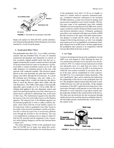
The QIT (Fig. 4) is constructed of three electrodes. (The
energy ions follow through the rod structure. At a given
term“quadrupole,”then,canbeconfusing,butemphasizes
DC potential and rf frequency, only ions within a cer-
the relationship of this device to the quadrupole mass fil-
tain mass range follow a stable ion trajectory that allows
ter.) The doughnut-shaped central (ring) electrode is sand-
them to reach the detector rather than collide with the
wiched between two end-cap electrodes. In the simplest
rods themselves. The width of that range is electronically
incarnation of the QIT, a gated electron beam from a fila-
adjustable, and is usually set to be 1 Da in width. The os-
ment enters through a small aperture in one of the end-cap
cillating field applied to the rods alternately attracts and
electrodes to cause ionization of gas-phase neutral sam-
repels ions passing through the mass filter, inducing an ion
ple molecules resident in the central portion of the device.
motion that is exploited to differentiate ions on the basis
The other end-cap electrode also has an aperture through
of their mass. The mathematical equation that describes
which selected ions reach the electron-multiplier detector.
the motion of the ions in this field is known as the Mathieu
All electrodes present a hyberbolically curved surface to
equation. The reduced form of the Mathieu equation can
the central cavity.
be presented graphically in what is called a stability dia-
gram, which shows both the several stability regions for
ion trajectories within a quadrupole mass filter, based on
the values of the electronic parameters, and the scan func-
tion that is followed to pass ions of successively different
mass through the structure to the ion detector. The scan
is accomplished by scanning across a range of values for
both the DC potential and the amplitude of the rf poten-
tial, while keeping frequency and the ratio between them
constant (ref ).
The initial advantage (1970s) of the quadrupole mass
filter for GC/MS was its faster scan speed than sector-
based instrumentation. In addition, the small physical size FIGURE 4 General diagram for an ion trap mass analyzer.