
Page 268 - Academic Press Encyclopedia of Physical Science and Technology 3rd Analytical Chemistry
P. 268
P1: GTM/GRL P2: GNH Final Pages
Encyclopedia of Physical Science and Technology EN009N-406 July 18, 2001 23:32
156 Mass Spectrometry
whether it is the next discrete dynode, or further down the
tube of a continuous dynode device. The electrons acquire
a kinetic energy equal to the potential difference between
their point of origin and their next point of collision with
the surface. Electrons typically gain a few tens of eV of
energy in each transition, sufficient energy to cause the
release of several more electrons. Two electrons initially
released by positive ion impact generate 4 electrons at
the second impact and release event. As the process is
repeated, the four electrons become 8, and so on. A cas-
cading effect is established such that each incident particle
at the front of the device produces an amplified current of
electrons at the output. The gain of the device is ultimately
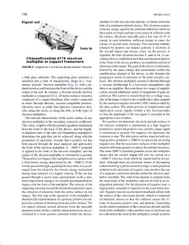
FIGURE 5 Diagram for a continuous dynode electron multiplier.
limited by the space charge that accumulates within the
amplification channel of the device, as this disrupts the
a bulk glass substrate. The supporting glass structure is progressive travel of electrons to the more positive sur-
stretched into a tube of characteristic shape in a “con- faces. The electron multiplier current is directed through
tinuous dynode” electron multiplier (Fig. 5), with a de- a vacuum feedthrough to a low-noise preamplifier, and
fined resistive path between the front of the device and the then to an amplifier. Between these two stages of amplifi-
output at the end. In contrast, a discrete dynode electron cation, several additional orders of magnitude of gain are
multiplier is composed of 12–20 metal surfaces (dynodes achieved. The current is transformed into a voltage (usu-
composed of a copper-beryllium alloy oxide) connected ally in the range of microvolts to millivolts), then sampled
in series through discrete, vacuum-compatible resistors. by the analog-to-digital converter (ADC) and recorded by
Electrons move in paths that intersect consecutive dyn- the data system. The entire process of amplification and
odes along the series, or along the tube, in both types of digitization occurs rapidly (within a few microseconds)
electron multipliers. so that the amplitude of the ion signal is recorded in the
The relevant characteristic of the active surface in any appropriate mass window.
electron multiplier is the secondary emission coefficient. For positive ion detection, the front dynode surface of
This value, coupled with the potential gradient maintained the electron multiplier is maintained at a high negative
from the front to the back of the device, and the length- potential to attract the positive ions, and the output signal
to-diameter ratio of the tube (in Channeltron multipliers) is referenced to ground. For negative ion detection, the
determines the gain that can be achieved, along with the converse is true. The first active surface must be held at a
parameters of operation. Assume that a positive ion has high positive potential (+2000 V) to attract the incoming
been passed through the mass analyzer and approaches negative ion. But the successive surfaces of the multiplier
the front of the electron multiplier. A −2000 V potential must be still more positive to attract the emitted electrons.
is applied to the front of the electron multiplier, and the The same 2000 V potential gradient across the multiplier
output of the electron multiplier is referenced to ground. means that the current output will now be carried on a
The positive ion impacts the multiplier active surface with +4000 V reference from which the signal must be decou-
a final kinetic energy determined by the −2000 V. If the pled. Although there are electronic means of decoupling
ion has passed through a quadrupole mass filter, it is accel- (often involving a photoconversion step), a more practical
erated from the relatively low kinetic energy maintained solution to the detection of negative ions involves the use
during mass analysis to a higher velocity. If the ion has of a separate conversion dynode within the electron mul-
passed through a sector mass spectrometer (with a rela- tiplier assembly. The conversion dynode is separate from
tively high kinetic energy), it is usually decelerated before the main body of the multiplier, and can be held at an in-
impact with the front of the multiplier. The velocity of the dependent potential. For the detection of negative ions, a
impacting ion must exceed the threshold required to cause high positive potential is imposed on the conversion dyn-
the emission of electrons from the active surface on ion ode. Negative ions are accelerated toward and collide with
impact. The first step in the operation of the multiplier is the surface of the conversion dynode, which is composed
therefore the transformation of a primary positive ion im- of materials chosen so that the collision causes the re-
pact into a release of electrons from the active surface. The lease of electrons, positive ions, and photons. Depending
ion impact releases several electrons from the specially on the relative potentials of the conversion dynode and the
prepared active surface, and the released electrons are ac- front of the multiplier, either positive ions or electrons can
celerated to a more positive potential within the device, be collected at the front of the multiplier; usually positive