
Page 96 - Academic Press Encyclopedia of Physical Science and Technology 3rd Analytical Chemistry
P. 96
P1: GRB Final Pages
Encyclopedia of Physical Science and Technology EN005M-206 June 15, 2001 20:25
174 Electrochemistry
For a reversible process the peak potential can be re-
lated to the polarographic half-wave potential, E 1/2 ,by
the expression
RT 0.0285
E p = E 1/2 − 1.11 = E 1/2 − at 25 C
◦
nF n
(69)
Another useful parameter of the voltammetric curves is the
half-peak potential, E p/2 , which is the potential at which
the registered current reaches half its maximum value and
is used to characterize a voltammogram. For a reversible
process, E 1/2 is located halfway in between E p and E p/2 .
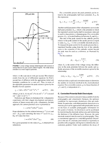
The ratio of the peak current for the cathodic process
relative to the peak current for the anodic process is equal
to unity (i p,c /i p,a = 1) for a reversible electrode process.
To measure the peak current for the anodic process the ex-
trapolated baseline going from the foot of the cathodic
wave to the extension of this cathodic current beyond
the peak must be used as a reference, as illustrated by
Fig. 4.
For the condition
0.141
|E λ − E p/2 |≥ , (70)
n
where E λ is the extent of the voltage sweep, the differ-
FIGURE 4 Linear voltage-sweep voltammogram with reversal of
ence in the peak potentials between the anodic and ca-
sweep direction to give a cyclic voltammogram. The initial sweep
direction is to more negative potential. thodic processes of the reversible reaction is given by the
relationship
0.059
where ν is the scan rate in volts per second. This relation | E p |=|E p,a − E p,c |= at 25 C, (71)
◦
results from the set of differential equations for Fick’s n
second law of diffusion (with the appropriate initial and which provides a rapid and convenient means to determine
boundary conditions for ox and red ). Thus, in terms of the number of electrons involved in the electrochemical
the adjustable parameters the peak current is given by the reaction. For a reversible system, i p is a linear function of
Randles-Sevcik equation √ ν, and E p is independent of ν.
b 1/2
5 3/2
◦
i p = 2.69 × 10 n AD 1/2 C ν at 25 C, (66)
2
2 −1
b
where i p is in A, A is in cm , D is in cm s , C is in mol C. Controlled-Potential Bulk Electrolysis
−3
−1
cm , and ν is in V s .
Because of the extensive amount of data available from the
Nicholson and Shain revolutionized the voltammetric
polarographic and voltammetric literature, the optimum
experiment with their elegant development and demon-
conditions for macroscopic electrolyses often are estab-
stration of linear-sweep and cyclic voltammetry. In their
lished. In particular, controlled-potential electrolysis at a
approach, the current-potential curve is presented as
mercury pool can be approached with predictable success
b
i = nFAC (πDa) 1/2 χ(at). (67) on the basis of available polarographic information for
the system of interest. An electrolysis can be accelerated
From tabulations for the relation between π 1/2 χ( at) and by maximizing the electrode surface area and minimizing
n(E − E 1/2 ) and converting the term π 1/2 χ(at)to χ rev , the thickness of the diffusion layer. However, the same
Eq. (67) takes the form electrode material must be used as in polarography. Thus,
b
i = nFAC (Da) 1/2 χ rev . (68) a conventional approach in controlled-potential electrol-
ysis is the use of a mercury pool stirred as vigorously as
For a given potential (E) the value of χ rev is obtained from possible with a magnetic stirring bar to minimize the con-
tabulations. centration gradient. Under such conditions the decay of