
Page 115 - Engineered Interfaces in Fiber Reinforced Composites
P. 115
98 Engineered interfaces in fiber reinforced composites
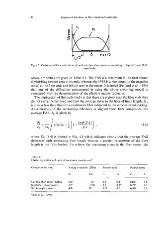
Fig. 4.2. Variations of fiber axial stress, 0;. and interface shear stress, zi, according to Eqs. (4.1) and (4.2),
respectively.
whose properties are given in Table 4.1. The FAS is a maximum in the fiber center
diminishing toward zero at its ends, whereas the IFSS is a maximum (in the negative
sense) at the fiber ends and falls to zero in the center. It is noted (Feillard et al., 1994)
that one of the difficulties encountered in using the above shear lag model is
associated with the determination of the effective matrix radius, b.
The implication of this early study is that there are regions near the fiber ends that
do not carry the full load and that the average stress in the fiber of finite length, 2L,
is always less than that for a continuous fiber subjected to the same external loading.
As a measure of the reinforcing efficiency in aligned short fiber composites, the
average FAS, Of, is given by
0, Loa J -1 \-/- (4.4)
0
where Eq. (4.4) is plotted in Fig. 4.3 which indicates clearly that the average FAS
decreases with decreasing fiber length because a greater proportion of the fiber
length is not fully loaded. To achieve the maximum stress in the fiber center, the
Table 4.1
Elastic properties and radii of composite constituentsa
Composite systems Young's modulus (GPa) Poisson ratio Radius (mm)
Ef Em Vf Vm a b
Carbon fiber-epoxy matrix 230 3.0 0.2 0.4 0.003 1 .o
Steel fiber-epoxy matrix 179 2.98 0.3 0.35 0.275 6.5
Sic fiber-glass matrix 400 70 0.17 0.2 0.071 2.8
aKim et al. (1992).